Arduino ProtoShield Quickstart Guide
This Tutorial is Retired!
View the updated tutorial: SparkFun Arduino ProtoShield Hookup Guide
 jimblom,
  bboyho
Hardware Assembly
Congratulations on your purchase of the SparkFun Arduino ProtoShield Kit!
Well, now what? The focus of this guide is to aid you in turning that box of parts in front of you into a fully functional prototyping shield. I'll also share some usage hints to help you get the most out of your shield.
Assembly Preparation
First, check to make sure you've got everything you need. Your kit should come with the following:
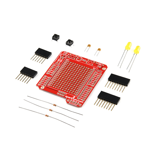
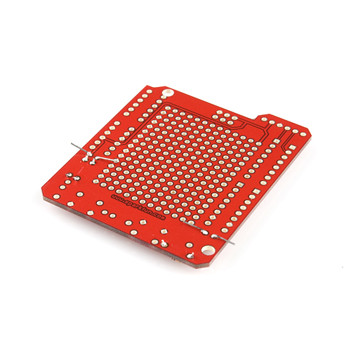
- 1x ProtoShield bare PCB
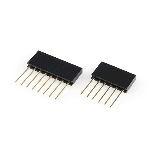
- 2x Stackable Headers 6-pin
- 2x Stackable Headers 8-pin
- 2x 5mm Basic Yellow LEDs
- 2x 330 Ohm resistors
- 1x 10k resistor
- 2x Momentary push buttons
- 2x 0.1uF Ceramic Capacitors
Missing any parts? (Bad SparkFun kitters!) Drop our customer service team an email. We'll get them out to you as soon as possible.
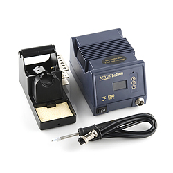
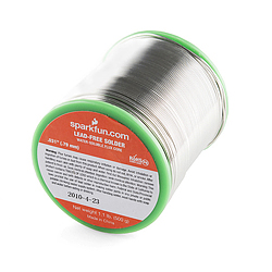
Moving on, you will need a few tools of your own to assemble the shield. Most importantly, you'll need a soldering iron and some solder. All of the soldering is through-hole, so even the most basic of soldering irons should do.
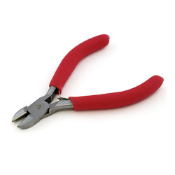
You'll need to do quite a bit of leg clipping; for that, you can't go wrong with SparkFun-ized diagonal cutters! Beyond that needle nose pliers can be super helpful if you want to perfectly bend your components!

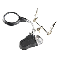
A third hand is always a helpful tool when soldering, especially with through hole components.
Assembly Instructions
If this is your first time soldering, that's OK! This is a great kit for first-time solderers. However, I'd really recommend checking out our introductory soldering tutorial first. Read the guide and you'll pick up some good tips that will help your first soldering experience go more smoothly.
I usually like to focus on soldering the smaller parts on first. If you prefer putting the parts in in a different order, don't let this tutorial stop you! Keeping that in mind, let's start with the resistors:
Resistors
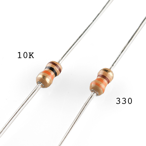
The ProtoShield comes with three resistors: two 330Ω and one 10kΩ. These resistors are all marked with standard color codes; the two 330Ω'ers should have an orange-orange-brown-gold band pattern, while the 10kΩ should be brown-black-orange-gold. It never hurts to double-check the values with your multimeter, if you have one handy. There is about a 5% tolerance on the resistors, so don't worry if your 10k reads 9.8k or 10.2k, it will still work.
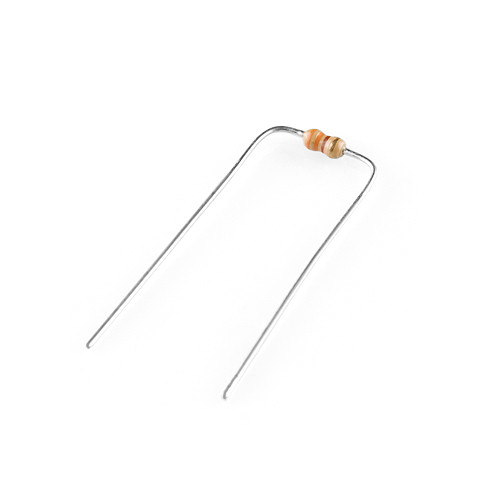
The resistors will go in the rectangular boxes labeled, obviously, either '330' or '10k'. I like to pre-bend the resistor leads, before I stick them into the board; bend both legs just a tiny bit beyond the body of the resistor, in the same direction. You can use your pliers or just your fingers for this job.
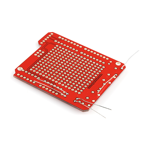
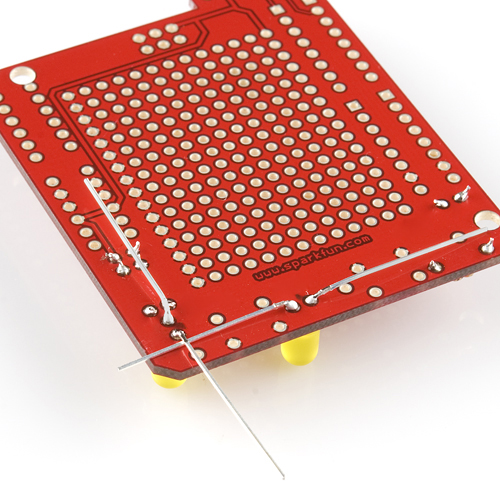
Now stick the resistor into the top side of the board. Make sure you check one last time that the value is correct! Resistors are not polarized, so you can stick them in in either direction. Once it's in, I like to turn the board over and bend the protruding legs out to keep the resistor in place. Solder the legs of the resistors on the bottom of the board. Try to keep the resistor as flush with the board as possible.
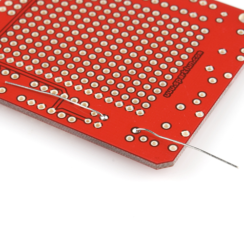
Now, bend, solder and repeat two more times.
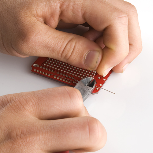
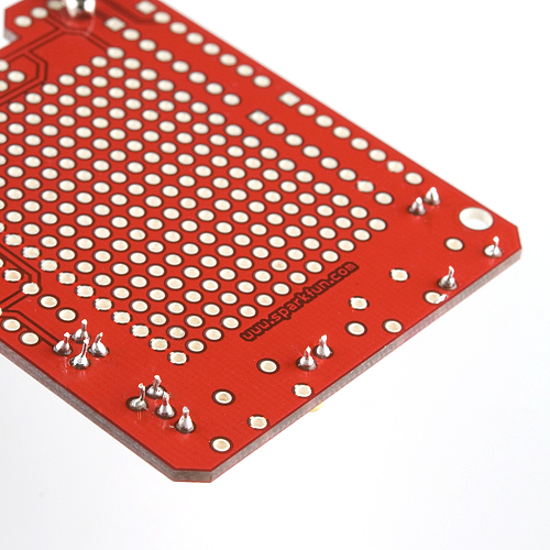
Once you've got the resistors all soldered up, you'll need to cut the remaining bits of the legs off. You don't want those legs touching each other when you power the board up! Remember to hold the end of the leg when clipping it, you don't want to hit your neighbor with projectile clippings.
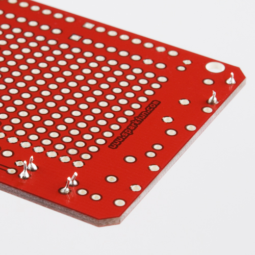
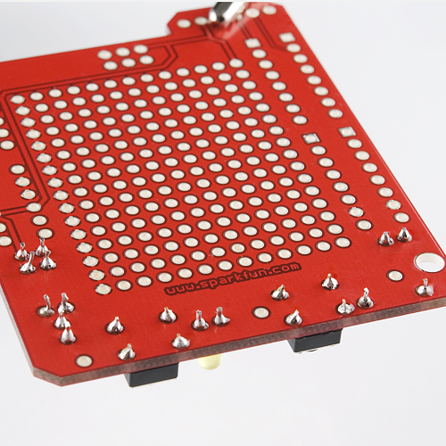
When you're done, it should look like this. Remember not to clip the legs too short as this could weaken the solder joints.
If you happen to solder the wrong resistor in the wrong place, you'll notice when you try to power the LEDs. The differences in the current will mean the LEDs will appear much dimmer. Although this shouldn't hurt your board, it's something to correct so you can get full functionality out of your ProtoShield.
Capacitors
Continuing with the smaller parts, let's solder on the capacitors next. You should have two 0.1uF capacitors, which are both ceramic and therefore non-polarized (you can stick them in either way).
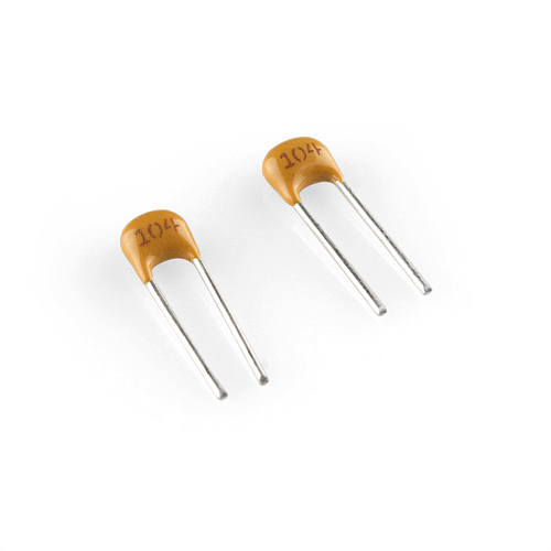
The two caps will go in the rectangular boxes with a line in the middle – there's one on each side of the board. They don't require any bending, or other preparation, just stick them in. Once they're in, I'd again recommend bending the legs to keep them in place. Now, solder both capacitors' legs on the bottom side of the board.
Cut the remaining parts of each leg as much as possible.
LEDs
The ProtoShield includes two LEDs for your blinky needs. This time, you are working with polarized parts, so make sure you install them correctly. You'll notice that one of the two legs on each LED is shorter than the other. The shorter leg is called the cathode, and the other is called the anode.
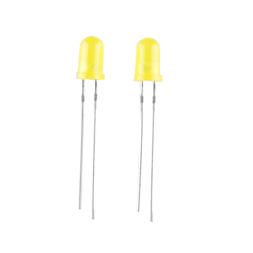
The LEDs will be installed in the two semi-circular footprints on the board. These semi-circles have a flat edge, which signifies where the cathode should go.
Insert the LED, making doubly-sure that the smaller leg is inserted in the hole nearer the flat part of the semi-circle. Flip the board over, bend the legs to keep the LED in place, and solder. Again, try to keep the bottom of the LED as flush as possible with the PCB.
And, of course, cut as much of the legs off as possible.
Buttons
These buttons are a nice change of pace – no bending or clipping necessary! You should have two buttons in your kit. By now, your ProtoShield should be getting pretty full, so it should be clear where these go – the square footprints, with a circle in the middle.
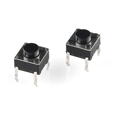
Line up the four legs of the button with the four holes on the PCB. It can fit in two different directions, and it doesn't matter which one you choose. After lining it up, press down on the button and you should feel a couple satisfying clicks as it finds it's place flush on the board. You may have to do a little guiding of the legs to encourage them into the hole.
Now turn the board over and solder all four pins of each button.
Headers
Almost there! All that remains are the four headers. The real challenge here is getting the headers straight and aligned with each other, such that the shield will effortlessly plug into your Arduino. You'll notice that each of the four headers has two possible locations that it could possibly plug into; make sure that each header goes on the outermost position. The inner pins are for all your prototyping needs later on.
Let's start with the 6-pin headers. Plug the first one into the top of the board and hold it in place as you turn the board over. Try to keep the header as parallel to the board as possible and solder one of the edge pins.
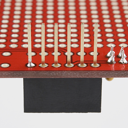
After soldering the first pin, take a look at the header to make sure it's nice and straight. If it looks off in either direction, or if the header isn't flush with the board, heat the leg back up and slide the header until it looks good. Another good test for the correct alignment of the header is to just plug it into your Arduino. Once the alignment looks OK, solder the leg on the other edge of the header.
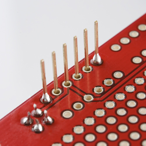
Soldering just those two pins should be enough to hold the header in-place for now. It also makes re-aligning the header a little easier, should the need arise later. Now, follow the last few steps with the second 6-pin header, making sure that it's as straight as the first 6-pin header. Once you're done, it doesn't hurt to do another plug-into-the-Arduino-to-check-the-alignment test.
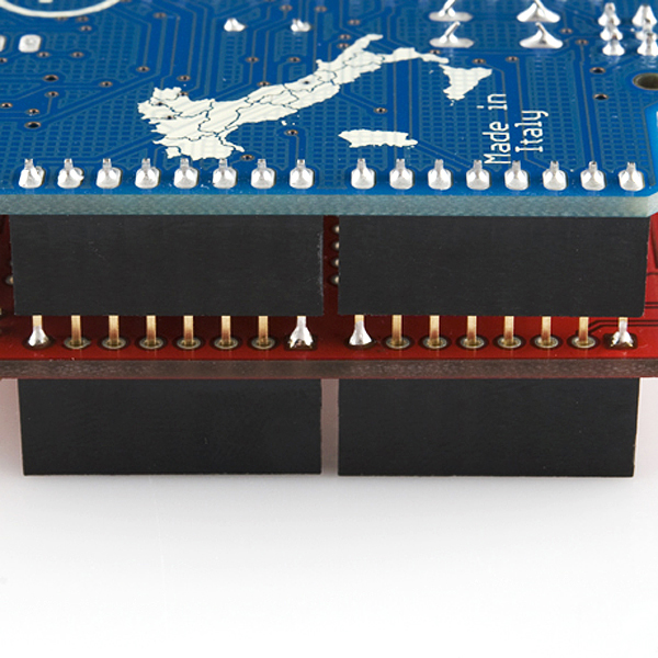
Now repeat the same steps with the 8-pin headers. You should have each header (somewhat) installed. Try plugging the shield into your Arduino. If all the headers are straight, it should go in fairly easily. Does everything seem nice and evenly aligned? Sweet! Unplug the board, flip it over and solder the remaining twenty pins.
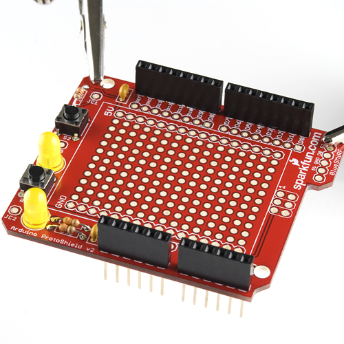
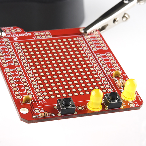
That's it! Your done! Hopefully, your board looks like this:
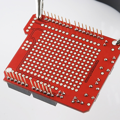
Now's the time to double check all your soldering and fix up any problems:
- Do the joints all look shiny and volcano shaped?
- Do you have any "shorts" or "bridges" between joints where you've accidentally connected the two joints with solder?
Check out the soldering guide for advice to avoid these problems. However, don't be too fussy; re-heating and moving the joints should be avoided if possible.
Adding the Finishing Touches
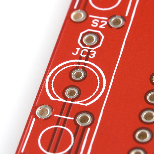
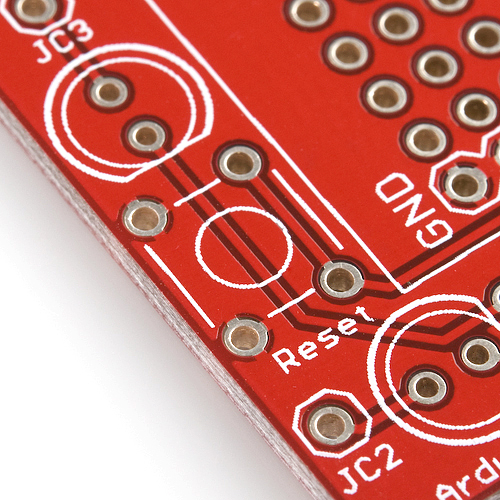
You've got the board assembled, but you've still got work to do. Both LEDs and the general use button aren't actually tied to anything, so your Arduino won't be able to do any LED blinking or button-press listening until you wire them up. While you were assembling the shield, you may have noticed a few lonely through-holes labeled 'JC1', 'JC2', and 'JC3'. These control the button and two LEDs, respectively. While it's completely up to you how you want to wire these bits up, here's a few things I've done with them:
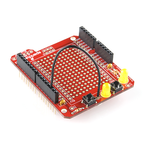
Wire the LEDs and Button Directly to Arduino Pins
If you've got any wire laying around, you can solder it directly into the JC# pin, and then connect the other end to whatever analog or digital pin you'd like. For example, the ProtoShield will cover up Arduino's LED tied to D13, so I usually like to wire one of the LEDs to that pin. Soldering a wire into JC3, I can the either plug the other end of the wire into the D13 pin on the stackable header, or solder it directly to the unused D13 pin. Another example would be to connect the JC2-connected LED permanently to the '5V' pin for use as a power indicator.
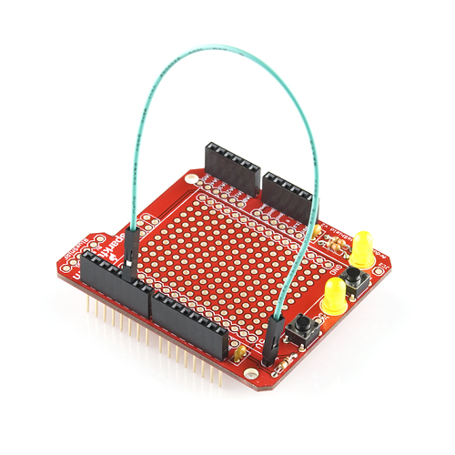
Solder in Single Headers into the JC# Through-Holes
Another method is to solder either male or female headers into the JC# pins. Then you can use some form of jumper wire to connect whichever Arduino pin you'd like to your LED/button of choice. This method keeps your ProtoShield reusable and as versatile as possible.
Using the Breadboard Area
You've finished the ProtoShield assembly, but, really, you haven't even started. The prototyping area is empty, and it's up to you how you want to use it. All of the pins in the breadboard area are spaced by 0.1", which is the same spacing on every one of our breakout boards. Or you could solder in a huge variety of DIP (dual in-line package) sized chips. The breadboarding area also has power and ground buses, as well as access to all of Arduino's digital and analog pins.
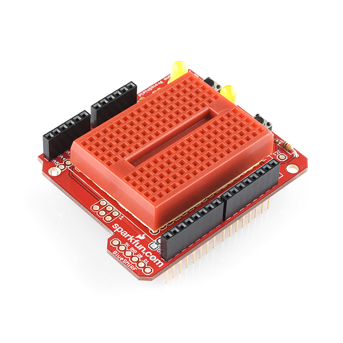
For those that prefer keeping their shield as reusable as possible, you can put a breadboard on top of the breadboarding area. We carry a variety of mini, self-adhesive breadboards that fit and stick perfectly onto the ProtoShield. Be warned, though, that this will cover up the '5V' and 'GND' buses (you still have access to these on the headers).
Bluetooth Arduino
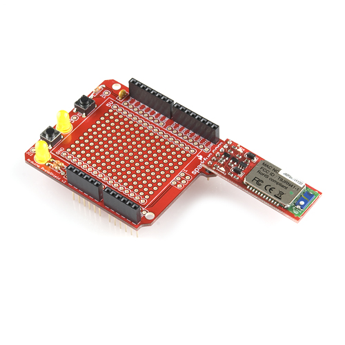
Finally, you may have noticed an unused, 6-pin header on the edge of the ProtoShield labeled 'BlueSMiRF'. The pin-out of this header matches up exactly with our BlueSMiRF Gold Bluetooth modem, which, when connected, wires up the modem directly to the necessary serial pins (D0 and D1) on your Arduino. The BlueSMiRF works as a simple, wireless replacement for serial cables. Any serial stream from 9600 to 115200bps can be passed seamlessly from your Arduino to the BlueSMiRF to your computer or almost any other Bluetooth enabled device. Just a little something to think about when you're prototyping your next project.
Enough! Time for you to start prototyping and making. And when your done tell us about your project!
Have a suggestion for how we can improve this guide? Steps missed? Instructions unclear? Please let us know. You can leave a comment below or email us spark@sparkfun.com. Also let us know if this is the most awesome assembly guide you've ever encountered and we'll stop trying to improve it.