Analog MEMS Microphone Breakout - SPH8878LR5H-1 Hookup Guide
 El Duderino,
  jenfoxbot
Hardware Assembly
Now that we're familiar with the microphone breakout, let's connect it to a microcontroller and monitor some sound!
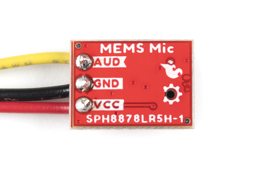
Microphone Breakout Connections
For a permanent connection, we recommend soldering three wires (or headers) to the PTHs on the breakout. We opted for soldering wires to the PTH connectors for a quick permanent connection to the breakout. For a temporary connection during prototyping, you can use IC hooks like these.
We recommend using the following colors of wire to easily distinguish the signals but you can always select a different color if you prefer (or do not have the colors used available).
- Red for VCC
- Black for GND
- Yellow (or some other color not Red or Black) for AUD
 |
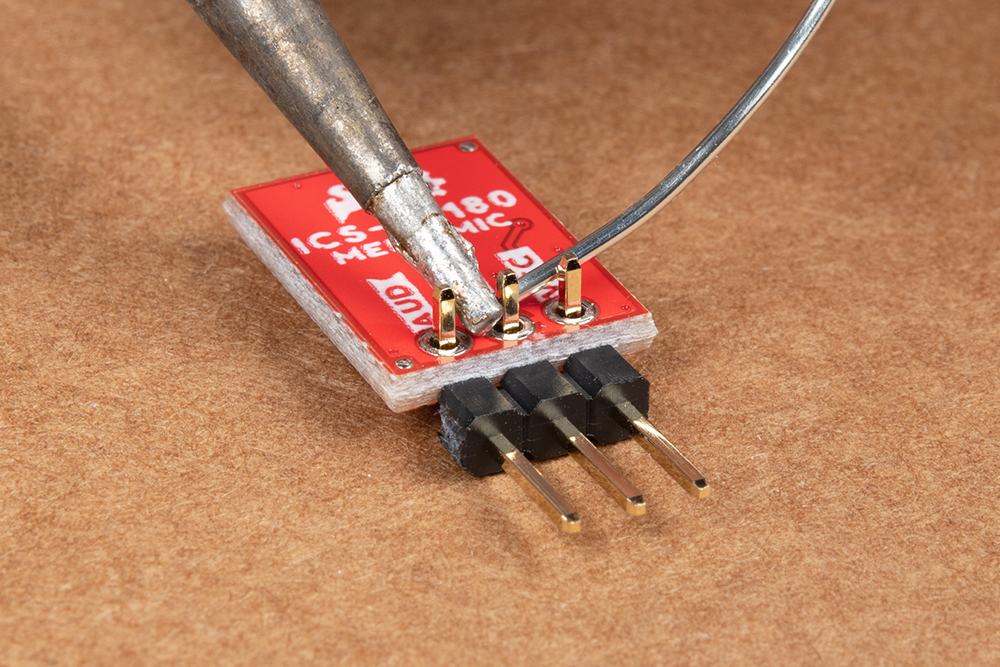 |
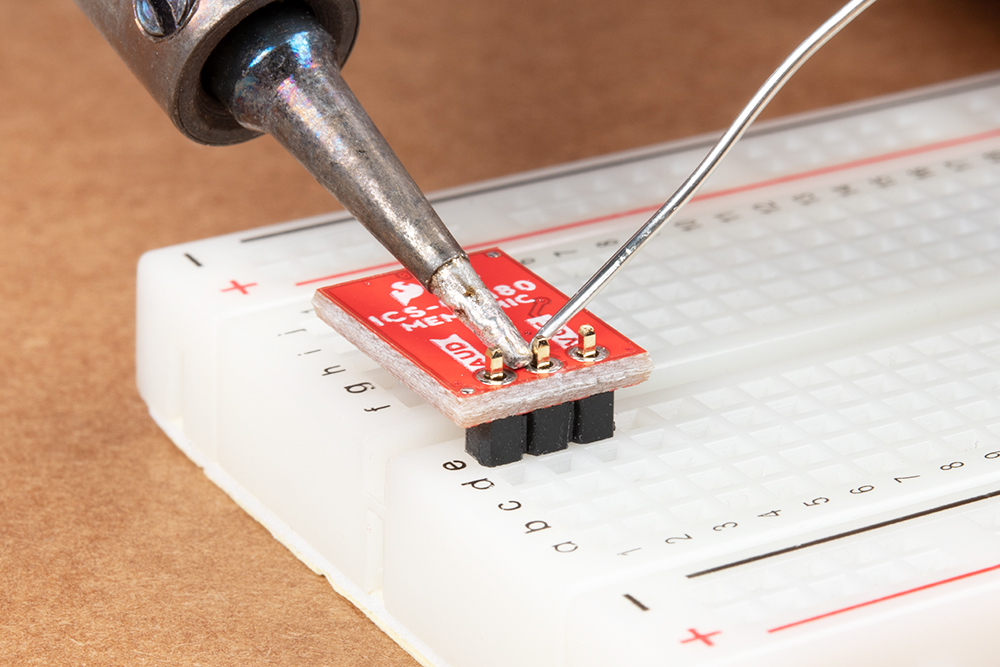
| Straight header pins being soldered to MEMS microphone. | Right angle header pins being soldered to MEMS microphone. |
Connecting to a Microcontroller
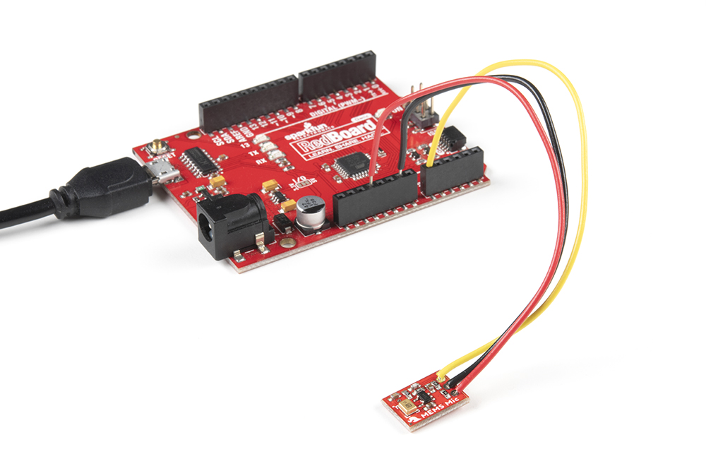
Next up we'll connect the breakout to a microcontroller we can use to monitor the audio signal output. For this tutorial, we used a SparkFun RedBoard Qwiic. Make the following connections between the breakout and RedBoard Qwiic (or whichever microcontroller you choose):
| RedBoard/Arduino | MEMS Microphone |
|---|---|
| A0 | AUD |
| GND | GND |
| 3.3V | VCC |
The completed circuit should look something like the photo below:
Read on to the next section for Arduino example code to monitor sound volume with the microphone breakout.