Air Velocity Sensor Breakout - FS3000 Hookup Guide
 QCPete, Ell C
Hardware Overview
FS3000
The FS3000 is a surface-mount type air velocity module utilizing a MEMS thermopile-based sensor. It features a digital output with 12-bit resolution and comprises a “solid” thermal isolation technology and silicon carbide coating to protect it from abrasive wear and water condensation.
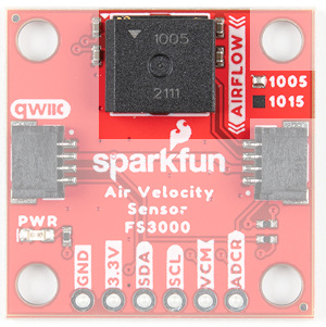
There are two versions of this sensor with different upper ranges (1005/1015). The 1005 version which can sense 0 to 7.23m/s (0 to 16.17mph) and 1015 version which can sense 0 to 15m/s (0 to 33.6mph). By looking at the PCB, there will be a solder blob indicating which version that you ordered and received. You can also check out the markings labeled on the IC. You'll also notice the arrow on the matching the silkscreen indicating what direction air should flow for a measurement. For the scope of this tutorial, we will be using the FS3000-1005 mostly to highlight the board and connect.
 |
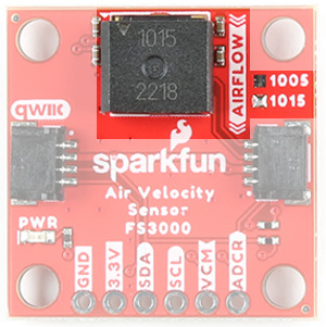 |
| FS3000-1005 [ SEN-18377 ] | FS3000-1015 [ SEN-18768 ] |
Below is a table of a few of the specifications taken from the datasheet. For more in depth information on this chip, please refer to the datasheet linked in the Resources and Going Further.
| Characteristic | FS3000-1005 | FS3000-1015 |
|---|---|---|
| Operating Voltage | 2.7V to 3.3V, typically 3.3V via Qwiic Connector | |
| Current Consumption | 10mA | |
| Air Flow Speed | 0 to 7.23 m/s (0 to 16.17 mph) | 0 to 15 m/s (0 to 33.6 mph) |
| Digital Output (Min to Max of Flow Range) | 409 to 3686 "count" | |
| Flow Accuracy | 5% @ 25°C | |
| Resolution | 12-bit | |
| I2C Address | 0x28 | |
| Operating Temperature | -20°C to 85°C | |
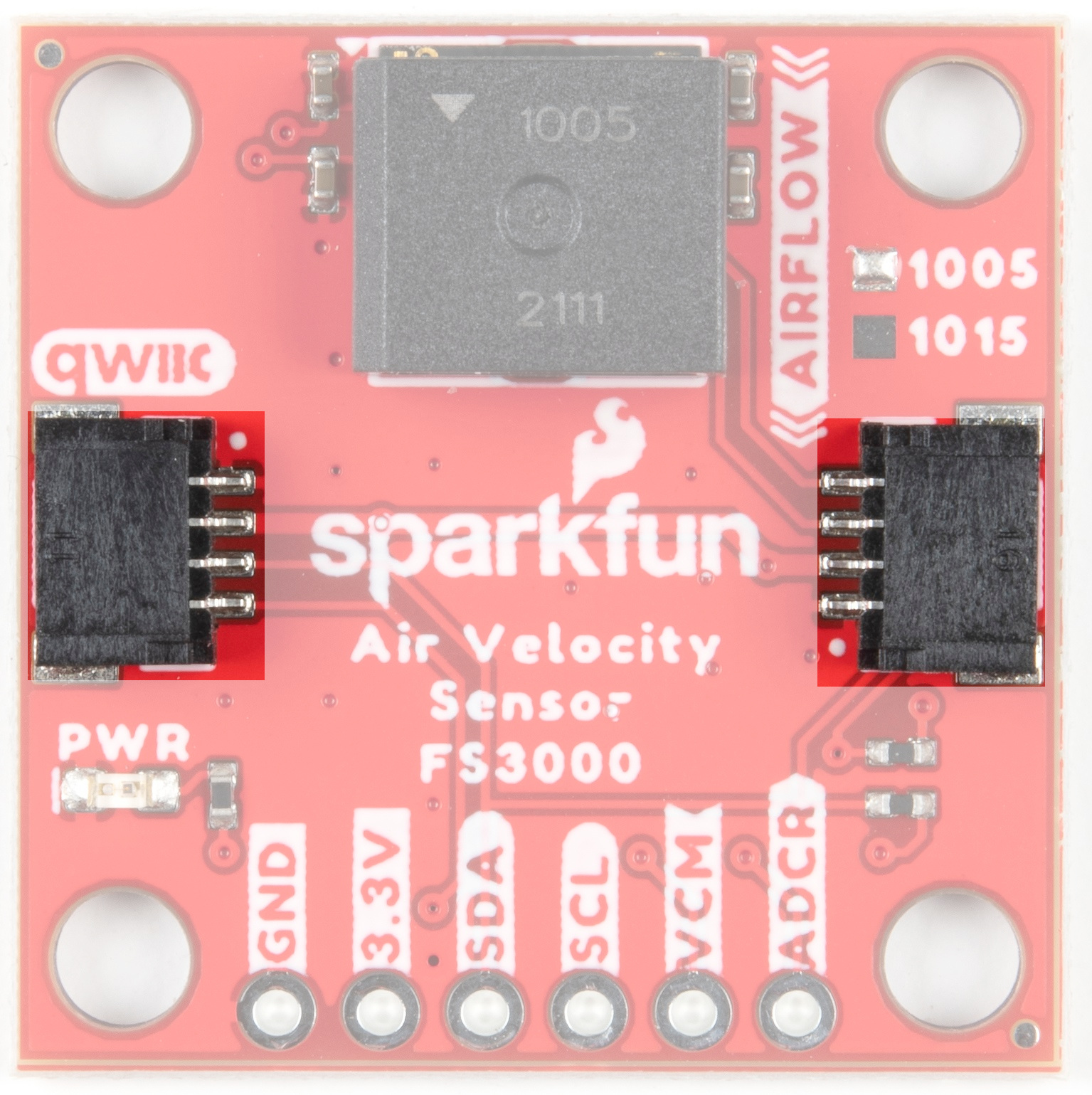
Qwiic Connectors
Our Qwiic Ecosystem makes sensors pretty much plug and play. There are two Qwiic connectors on either side of the Qwiic Air Velocity Sensor board to provide power and I2C connectivity simultaneously. The sensor's I2C lines are connected to two 2.2kΩ pull-up resistors. The I2C address of the board is 0x28.
Pins
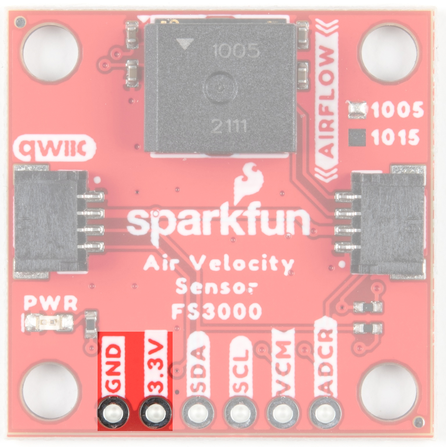
Power
Ideally, power will be supplied via the Qwiic connectors on either side of the board. Alternatively, power can be supplied through the header along the bottom side of the board labeled 3V3 and GND. The input voltage range should be between 2.7-3.3V. The usual current draw is around 10mA.
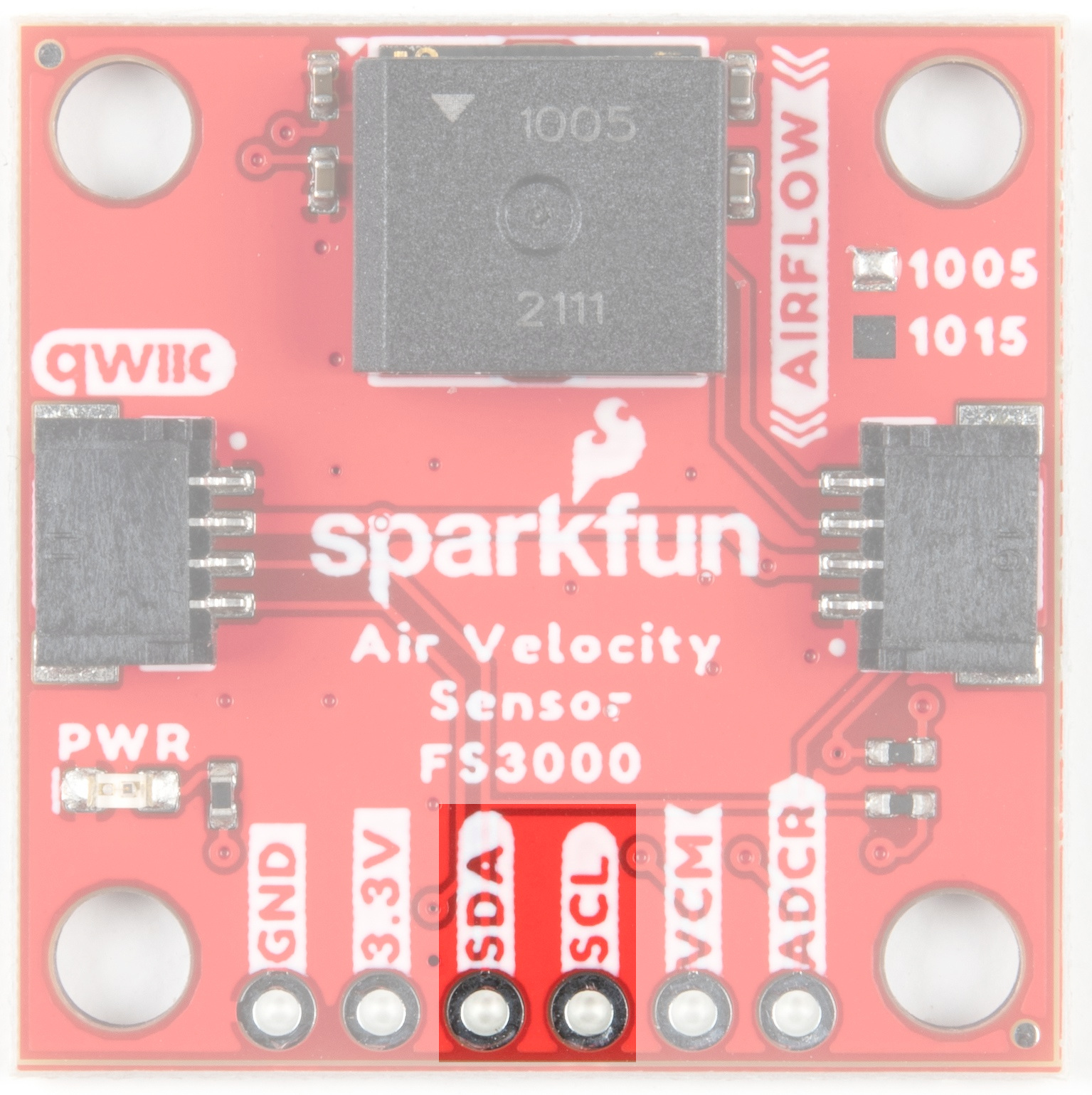
I2C
The I2C pins break out the functionality of the Qwiic connectors. Depending on your application, you can connect to these pins via the plated through holes for SDA and SCL.
VCM and ADCR
VCM is an output from the sensor that provides a common bias voltage. With a power supply voltage at 3.3V (usual for Qwiic), the VCM pin will output 1.25V. The current datasheet does not provide any more information about this pin, however, it is most likely a bias voltage used with some sort of analog gain stage internal to the sensor (prior to it's internal ADC). This can be useful for unique more advanced projects that may benefit from having a known bias voltage tied to another analog system.
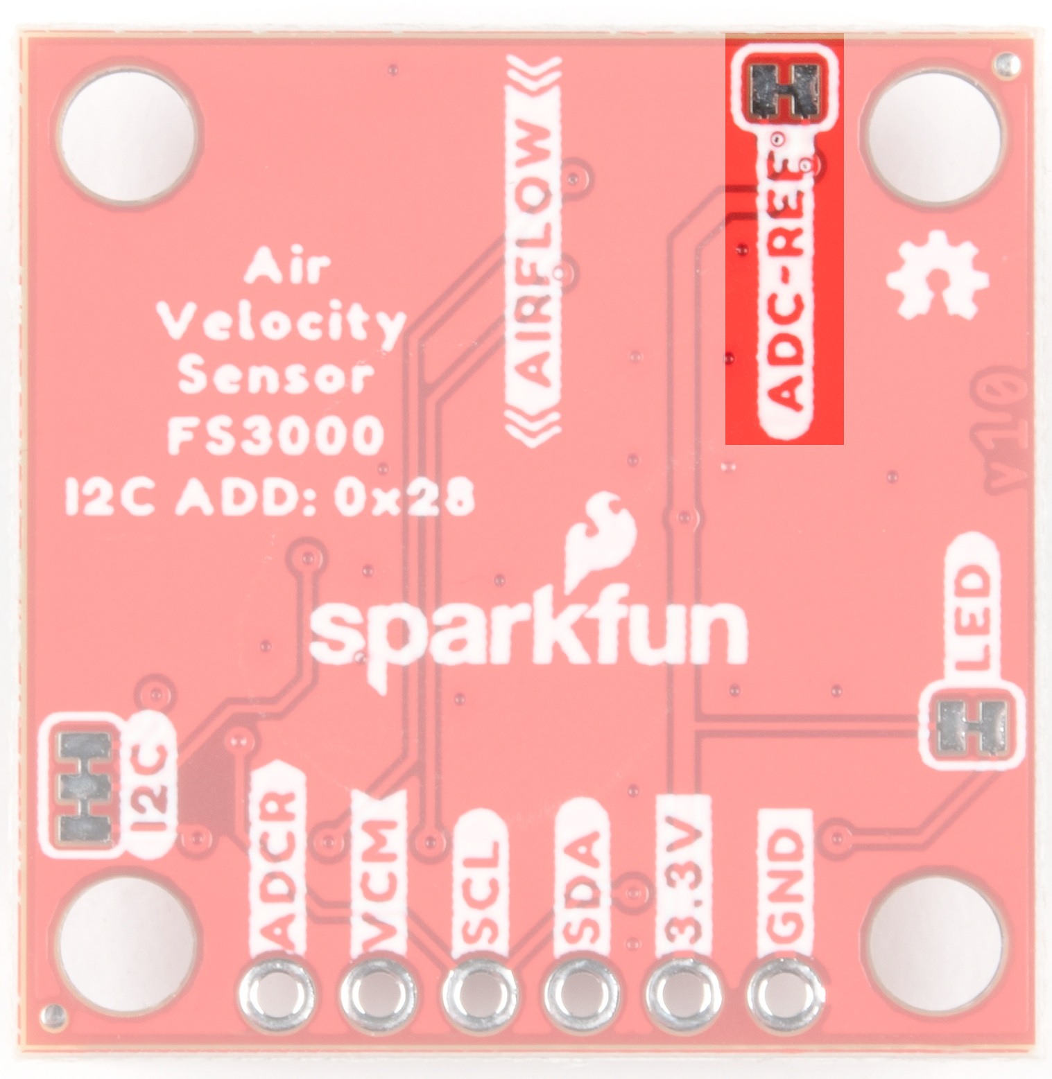
ADCR stands for ADC Reference. This is an input to the FS3000 which allows you to provide a reference voltage for the sensor's internal ADC. Note, you must first cut the "ADC-REF" jumper (on the bottom side of the board) before providing a custom voltage to this pin. By default, it is connected to VDD.

Jumpers
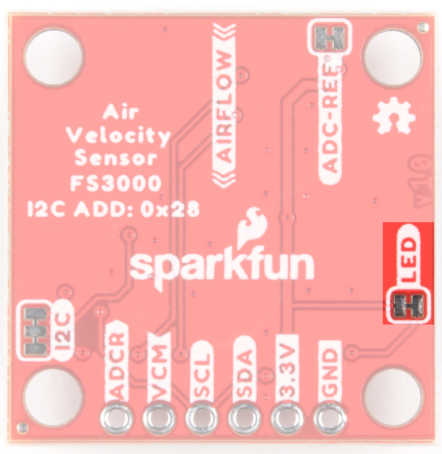
LED
If power consumption is an issue, cutting this jumper will disable the Power LED on the front of the board.
 |
 |
| PWR LED on Top Side |
LED Jumper on Bottom Side |
ADC-REF
Cut the ADC-REF jumper to provide your own custom ADC reference voltage on the ADCR header pin. By default (jumper closed), it is connected to VDD.
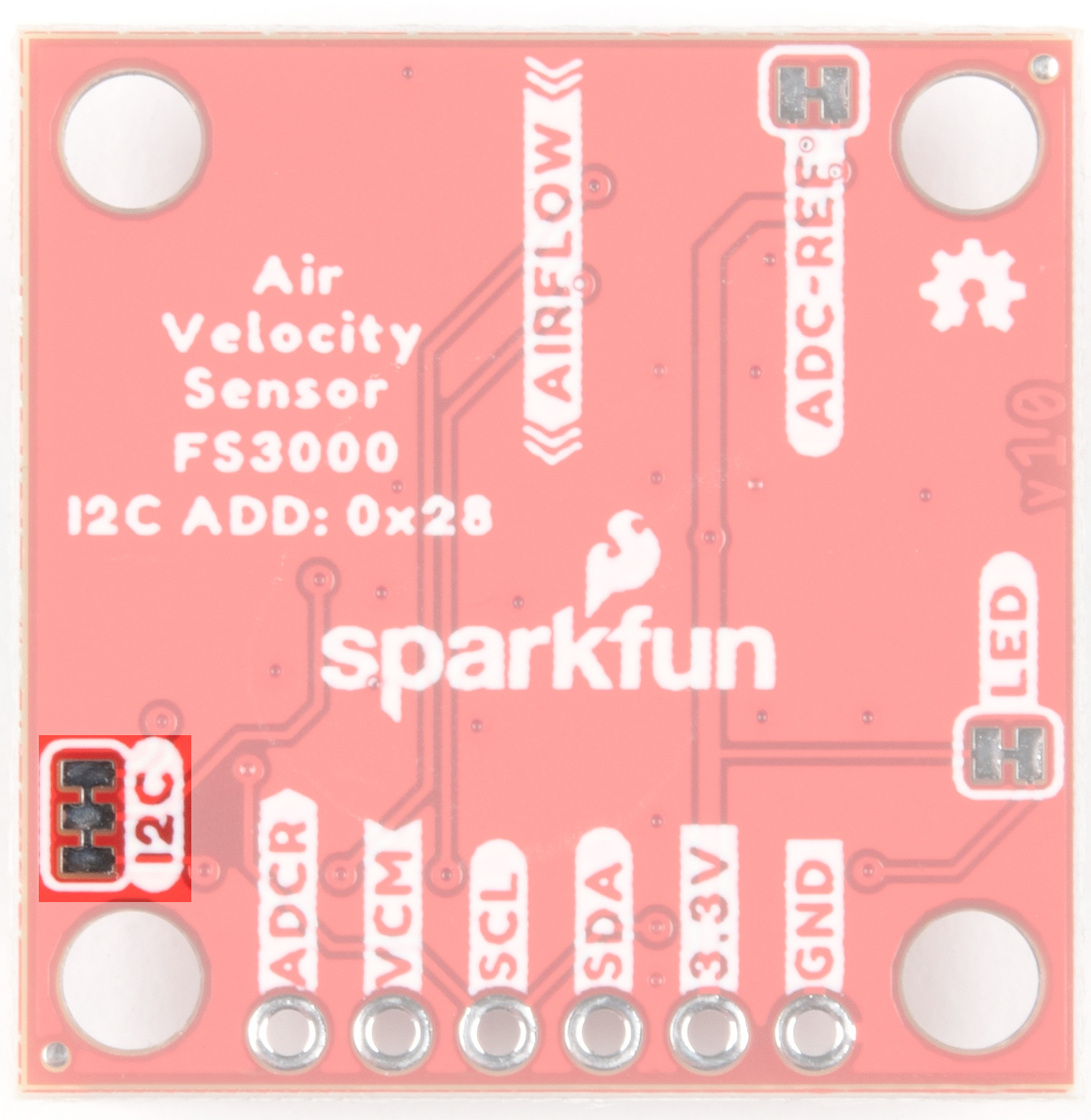
I2C
The SparkFun Air Velocity Sensor has pull up resistors attached to the I2C bus; if multiple sensors are connected to the bus with the pull-up resistors enabled, the parallel equivalent resistance will create too strong of a pull-up for the bus to operate correctly. As a general rule of thumb, disable all but one pair of pull-up resistors if multiple devices are connected to the bus. If you need to disconnect the pull up resistors they can be removed by cutting the traces on the corresponding jumpers highlighted below.
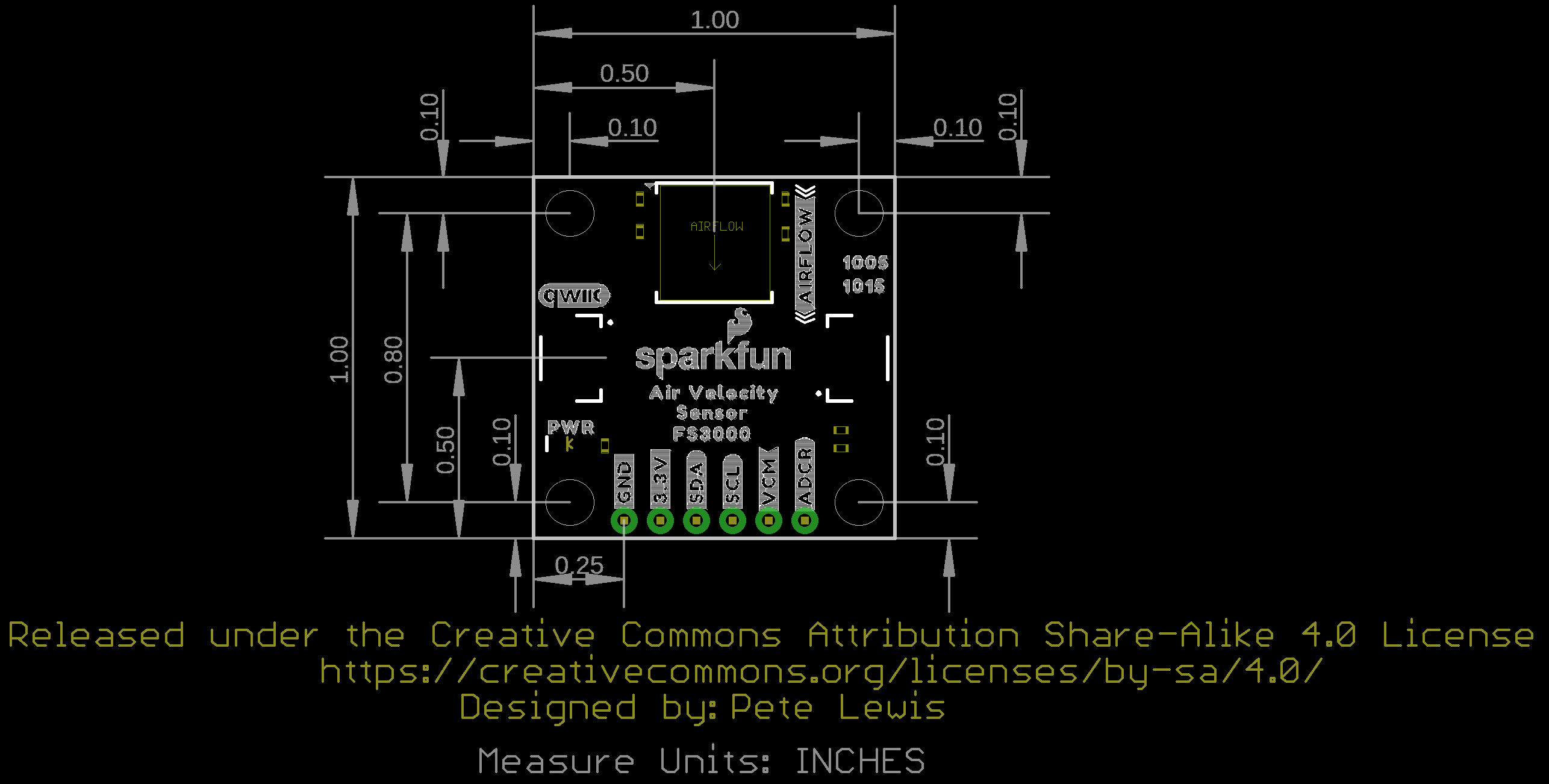
Board Outline