ADXL345 Hookup Guide
Calibration
The other sketch available to you is the SparkFun_ADXL345_Calibration.ino. This will be useful whenever you have an application that requires your device to be precision calibrated.
Calibration Method
An accurate calibration method is to use two points per axis. In our case we have a three-axis design, therefore, we are interested in six points. In the datasheet and in the example sketch, you'll notice references to the g range with accepted values of 2g, 4g, 8g or 16g. 1g is equivalent to the force of gravity acting on a stationary object resting on Earth's surface. Acceleration relative to gravity can be measured in units of gravitational force.
A great resource is the Application Note from Analog Devices: Using an Accelerometer for Inclination Sensing
Calibration Example Sketch
Here is what the calibration example sketch looks like:
language:c
#include <SparkFun_ADXL345.h>

/*********** COMMUNICATION SELECTION ***********/
/*    Comment Out The One You Are Not Using    */
//ADXL345 adxl = ADXL345(10);           // Use when you want to use Hardware SPI, ADXL345(CS_PIN);
ADXL345 adxl = ADXL345();             // Use when you need I2C

/****************** VARIABLES ******************/
/*                                             */
int AccelMinX = 0;
int AccelMaxX = 0;
int AccelMinY = 0;
int AccelMaxY = 0;
int AccelMinZ = 0;
int AccelMaxZ = 0;

int accX = 0;
int accY = 0;
int accZ = 0;

int pitch = 0;
int roll = 0;

/************** DEFINED VARIABLES **************/
/*                                             */
#define offsetX   0       // OFFSET values
#define offsetY   0
#define offsetZ   0

#define gainX     1     // GAIN factors
#define gainY     1
#define gainZ     1

/******************** SETUP ********************/
/*          Configure ADXL345 Settings         */
void setup()
{
Serial.begin(9600);                 // Start the serial terminal
Serial.println("SparkFun ADXL345 Accelerometer Breakout Calibration");
Serial.println();

adxl.powerOn();                     // Power on the ADXL345

adxl.setRangeSetting(2);           // Give the range settings
                                    // Accepted values are 2g, 4g, 8g or 16g
                                    // Higher Values = Wider Measurement Range
                                    // Lower Values = Greater Sensitivity

adxl.setSpiBit(0);                // Configure the device to be in 4 wire SPI mode when set to '0' or 3 wire SPI mode when set to 1
                                    // It is set to 1 by Default.
                                    // SPI pins on the ATMega328 as reference in SPI Library are 11, 12, and 13

}

/****************** MAIN CODE ******************/
/*  Accelerometer Readings and Min/Max Values  */
void loop()
{
Serial.println("Send any character to display values.");
while (!Serial.available()){}       // Waiting for character to be sent to Serial
Serial.println();

// Get the Accelerometer Readings
int x,y,z;                          // init variables hold results
adxl.readAccel(&x, &y, &z);         // Read the accelerometer values and store them in variables declared above x,y,z

if(x < AccelMinX) AccelMinX = x;
if(x > AccelMaxX) AccelMaxX = x;

if(y < AccelMinY) AccelMinY = y;
if(y > AccelMaxY) AccelMaxY = y;

if(z < AccelMinZ) AccelMinZ = z;
if(z > AccelMaxZ) AccelMaxZ = z;

Serial.print("Accel Minimums: "); Serial.print(AccelMinX); Serial.print("  ");Serial.print(AccelMinY); Serial.print("  "); Serial.print(AccelMinZ); Serial.println();
Serial.print("Accel Maximums: "); Serial.print(AccelMaxX); Serial.print("  ");Serial.print(AccelMaxY); Serial.print("  "); Serial.print(AccelMaxZ); Serial.println();
Serial.println();


/* Note: Must perform offset and gain calculations prior to seeing updated results
/  Refer to SparkFun ADXL345 Hook Up Guide: https://learn.sparkfun.com/tutorials/adxl345-hookup-guide
/  offsetAxis = 0.5 * (Acel+1g + Accel-1g)
/  gainAxis = 0.5 * ((Acel+1g - Accel-1g)/1g) */

// UNCOMMENT SECTION TO VIEW NEW VALUES
//accX = (x - offsetX)/gainX;         // Calculating New Values for X, Y and Z
//accY = (y - offsetY)/gainY;
//accZ = (z - offsetZ)/gainZ;

//Serial.print("New Calibrated Values: "); Serial.print(accX); Serial.print("  "); Serial.print(accY); Serial.print("  "); Serial.print(accZ);
//Serial.println();

while (Serial.available())
{
    Serial.read();                    // Clear buffer
}
}
The main code will read your accelerometer maximums and minimums. With these values we will be able to calculate the offset values and gain factors giving us our new calibrated accelerometer readings. We will talk more about the equations for those calculations in a minute.
Mounting Accelerometer
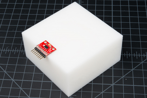
Before taking these measurements, we want to have the accelerometer mounted with the Z axis parallel to the up direction. For example, if our accelerometer is on a table, our ADXL345 breakout board will be oriented like the picture below and the Z data should be constant.
Make sure it's secure to either your application or a block that has a level flat surface.
Load Sketch and Take Measurements
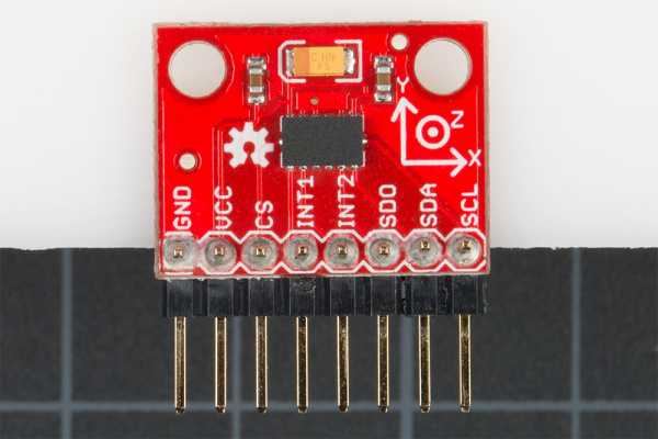
Load the Calibration Sketch to your board. Open the Serial Monitor, and wait for the prompt that says to Send any character to display values. Each time you want to measure a different axis, simply turn the enclosure or block the ADXL345 breakout is mounted on, type a character to the Serial Monitor, and hit return to print out the measurement result. You'll notice an X-Y-Z axis symbol on the breakout board that will help with orienting in each direction.
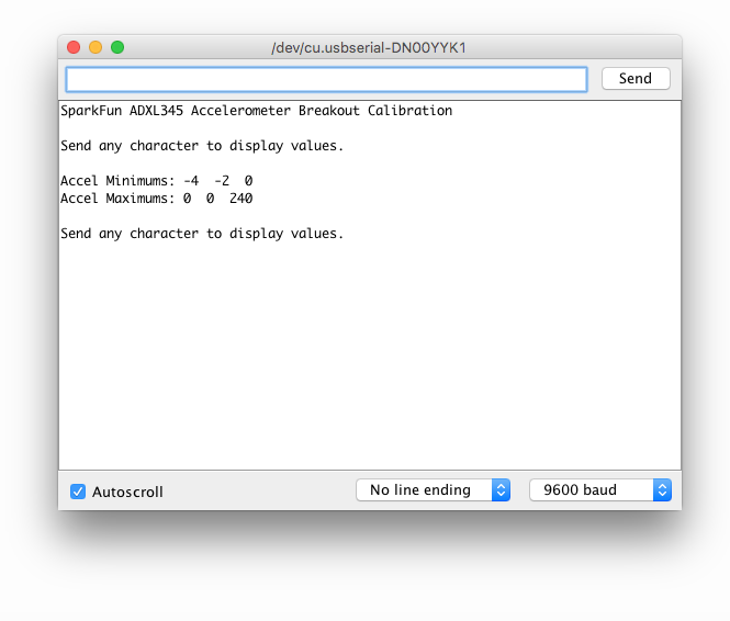
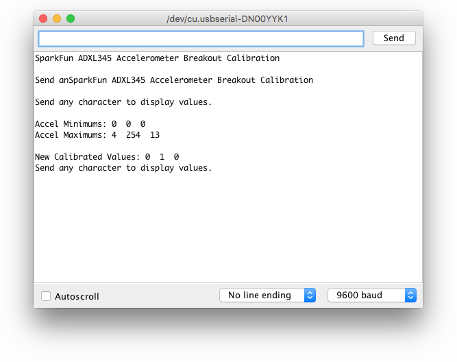
When an axis is placed into a +1 g and −1 g field, the measured outputs will look something like this on your Serial Monitor. You'll want to take measurements in each axis direction.
Recording Data
To leave room for offset and gain adjustments, it's probably best to do the calculations by hand. Record your data in a similar table like the one below.
| +1 g | -1 g | Offset | Gain | |
| X-Axis | ||||
| Y-Axis | ||||
| Z-Axis |
Calculations
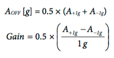
The offset values and gain factors are calculated with the following equations as stated in the Application Note from Analog Devices (page 8: equations 17 and 18).
In the DEFINED VARIABLES section of the code is where we will place the new calculated values for offset and gain.
language:c
/************** DEFINED VARIABLES **************/
/*                                             */
#define offsetX     0    // OFFSET values
#define offsetY     0
#define offsetZ     0

#define gainX       1     // GAIN factors
#define gainY       1
#define gainZ       1
Hooray! Now you'll be able to acquire the adjusted values for X, Y and Z.
Note: You'll have to uncomment a section of the following code to see your new calibrated values:
language:c
// UNCOMMENT SECTION TO VIEW NEW VALUES
accX = (x - offsetX)/gainX;         // Calculating New Values for X, Y and Z
accY = (y - offsetY)/gainY;
accZ = (z - offsetZ)/gainZ;

Serial.print("New Calibrated Values: "); Serial.print(accX); Serial.print("  "); Serial.print(accY); Serial.print("  "); Serial.print(accZ);
Serial.println();
Now your Serial Monitor output will be calibrated and look something more like this...
