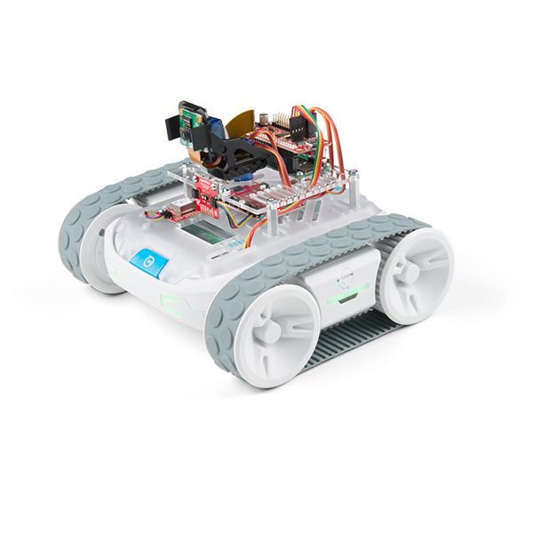
The SparkFun Advanced Autonomous Kit for Sphero RVR provides all the functionality of the basic kit with the addition of time-of-flight distance sensing in the front and rear. Based around Raspberry Pi’s small yet powerful Zero W model, the kit provides distance sensing, global positioning, and vision to the Sphero RVR. In this tutorial we'll cover assembly of the kit's hardware. Most of the steps are fairly straight forward and just require a little bit of patience.
To follow along with this tutorial, you will really only need a phillips-head screwdriver. We have quite a few to choose from - but our Pocket Screwdriver Set is a great option.
If you haven't already, start charging the RVR battery. It takes a while to charge, so now would be a good time to get it going.
You will need to build up the Pan-Tilt mechanism. We have instructions over in the Pan-Tilt Mechanism Section of our basic guide - head on over there now as you'll need to have this assembled in order to move forward with this tutorial!
 |
| Assembling the Pan-Tilt Mechanism Hookup Instructions |
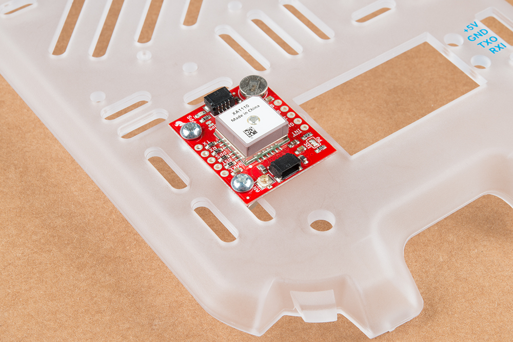
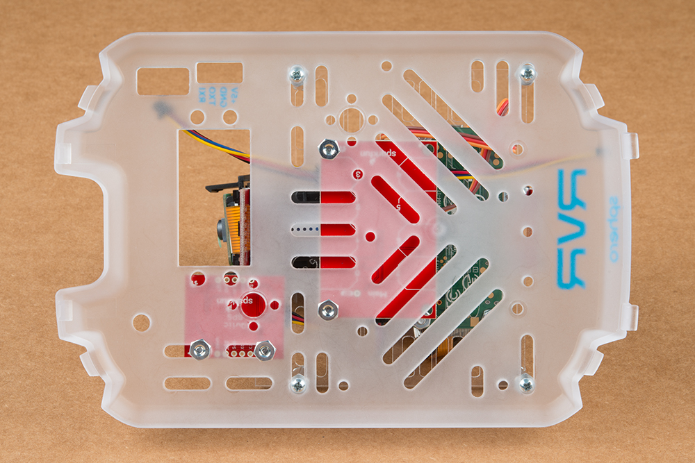
The GPS board and Mux board are the only two boards that will mount directly to the cover plate. It’s best to put these boards on first as the additional mounting plate obscures part of the board. We'll do this using two of the 1/4 inch screws and 2 nuts for each board.

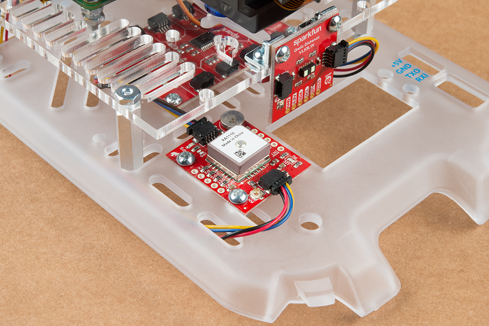
The antenna (the beige part on the board) will need to be unobstructed and pointed towards the sky, so we'll mount it off to the side and near the front of the cover plate on the inner set of slide holes. The Qwiic cable that runs from the Servo pHAT to the GPS will use the outer set of holes later. If you have the means, putting the GPS board up higher always helps, but be sure not to obscure the pan-tilt camera rig.
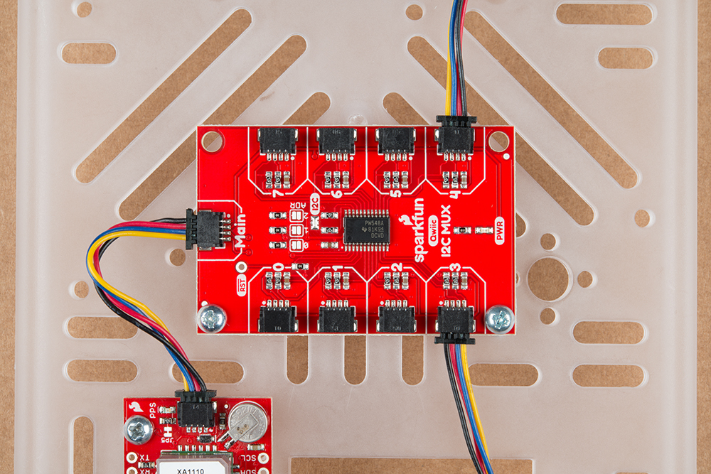
The Mux board will mount to the two screw holes in the middle of the RVR Cover Plate. it's important that the "Main" Connector is facing away from the labeled connector port on the RVR Cover Plate (see photo below).
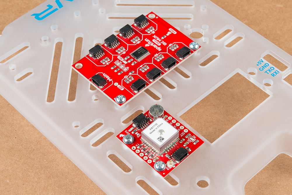
Once the Mux board is in place, we'll plug in the 50mm Qwiic cables (these might be 2x 100mm cables and 1 50mm cable in your kit) into the Mux board. We'll want one cable running from rear-facing Qwiic connector on the GPS board to the "Main" Qwiic connector on the Mux board. Then we'll plug one cable into connector 3 and a separate one into connector 4 on the Mux board (where you'll use the 2 100mm cables if you have them). We'll plug these into the Time of Flight sensors later in the tutorial. It's important to use connectors 3 and 4 (3 for the front facing Time of Flight sensor and 4 for the rear) as this corresponds to code in the example. If you want to change which connectors you're using, you'll have to change some parts of the code.
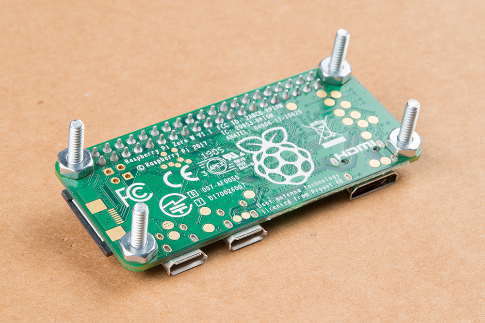
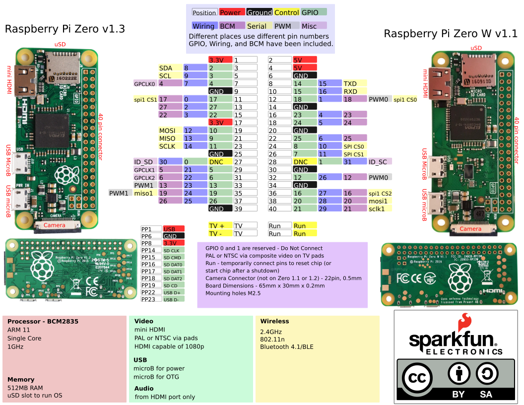
For the advanced kit, all four mounting points on the Pi Zero W will be used. Due to the through hole pins soldered to the Pi Zero W, you need to add a set of nuts between the board and the mounting plate. For this we'll use (4) 1/2 inch screws and (8) 4-40 nuts.
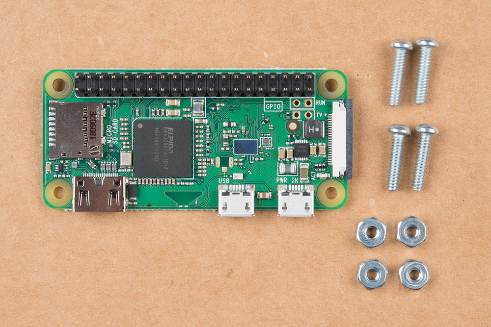
When complete, the Raspberry Pi Zero should look like this:
Do not mount the Raspberry Pi Zero yet, that will come at a later step.
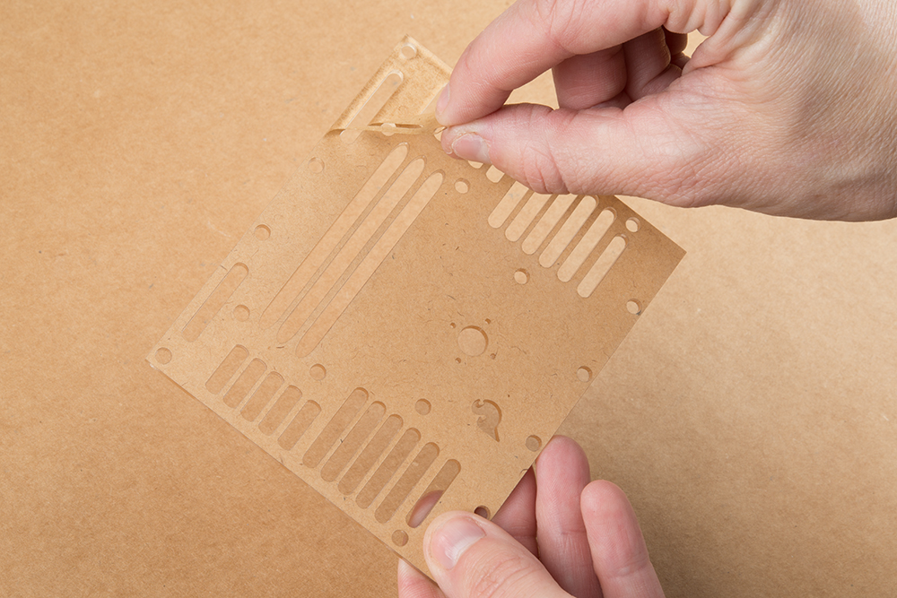
If you have not already, peel the protective layer off of the front and back of the acrylic plate.
The metal standoffs attach to the mounting plate with the 4-40 nuts. The threaded end of the standoffs will be facing up. Take extra care in tightening the nuts as you can crack the plate if you over-tighten them.
The time of flight sensors will need to be facing forward and backwards unobstructed. 4 right-angle mounting brackets have been included so the sensors can be mounted in the proper position on the mounting plate. The sensors can be added later, but it’s best to get these on the board before the pan-tilt rig is mounted. They're fastened to the mounting plate with a 1/4" screws and a 4-40 nut (for each bracket).
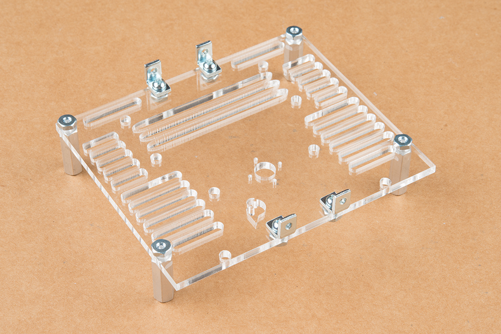
Note that the right-angle brackets have one threaded and one un-threaded hole. The threaded holes are smaller than the un-threaded holes, and if you look closely, you'll see the threads in the smaller holes.
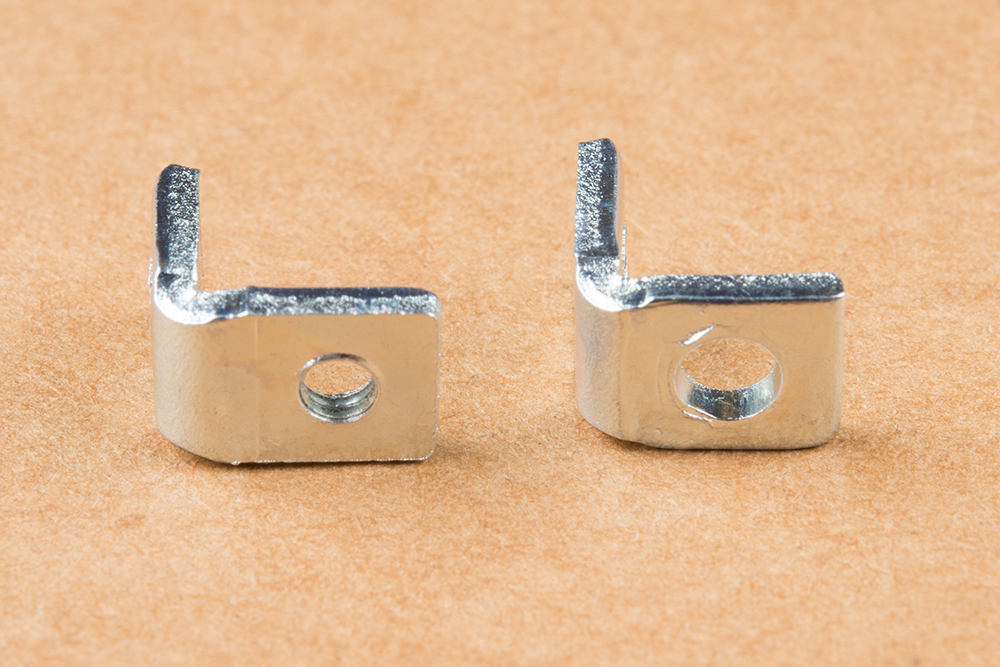
It’s important that the threaded holes are perpendicular to the plate, those will be the holes the screws that hold the sensor board in place use.
While the pan-tilt will be facing up, the servo horn (which the servo will be affixed to) is mounted on the bottom of the plate.
Line up the small holes on the plate with the small holes in the servo horn the same. Use the small, self-tapping screws to mount it in place from the top of the mounting plate.
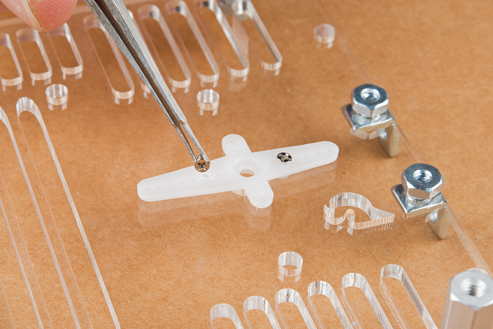
Two of the small self-tapping screws will suffice, but if desired you can use all four.
|
| Assembling the Pan-Tilt Mechanism Hookup Instructions |
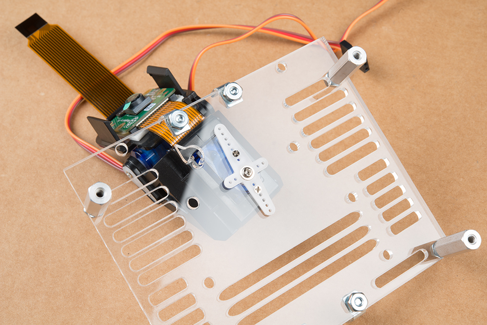
Once the horn is mounted in place, you can use the larger self-tapping screws to mount the pan-tilt rig. It’s important that the rig is mounted so that the middle of the servo travel faces forward. This will take some trial and error, but you want the servo to be able to move an equal amount in either direction when facing directly forward (it’s okay to move the servo when it isn’t powered, just don’t force it).
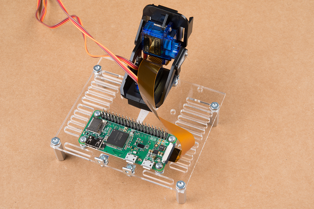
Add the Pi Zero W (with the spacer nuts installed) to the mounting plate with another 4 of the 4-40 nuts. For the best access to all the connectors on the Pi Zero, make sure the USB and HDMI Connectors are facing the back of the plate and the pins are facing the pan-tilt rig.

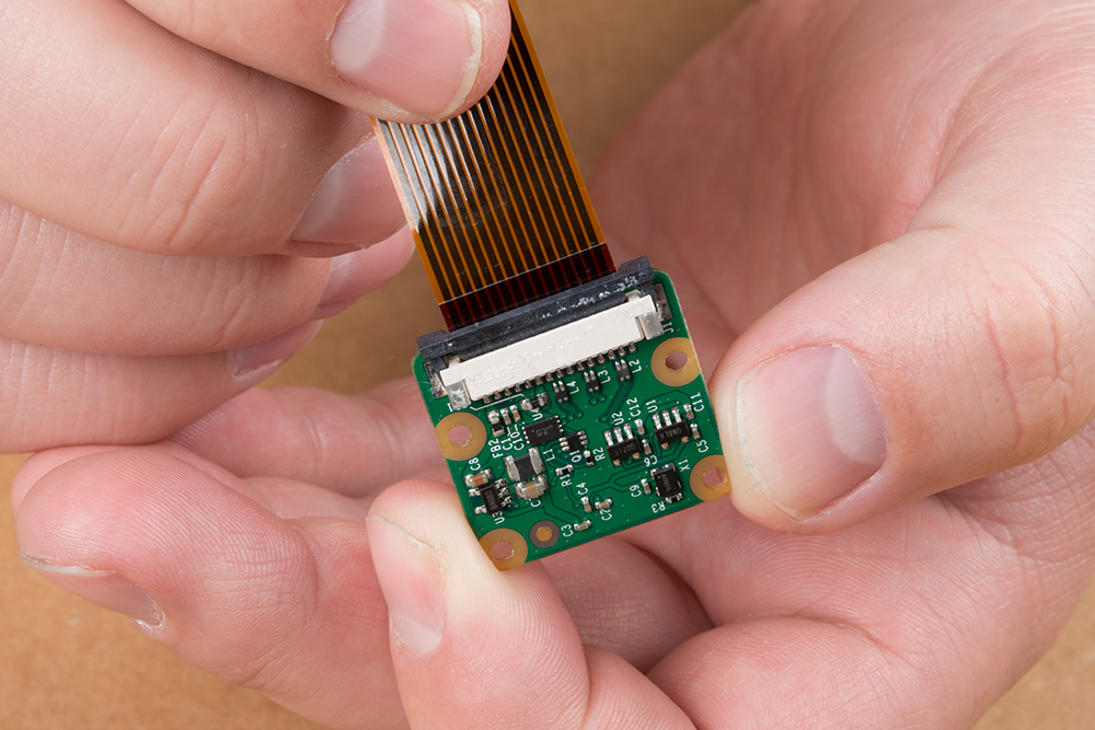
You'll need to mount the Raspberry Pi Camera to the pan-tilt mechanism using the included square of double sided tape. However, I recommend you plug in the camera to the ribbon cable before securing the camera to the tape square.
To connect the ribbon cable, you'll need to carefully slide the flexible ribbon cable connector's locking tab out. The locking tab slides out parallel to the board so you'll need to push each side of the tab with your fingernails. The image below highlights where you would need to place your fingernails to slide the tab out.
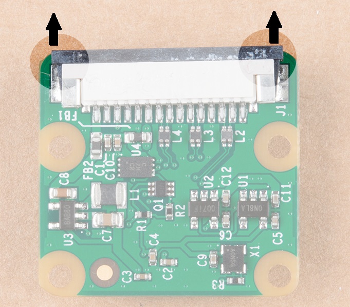
Once the locking tab is out, you can insert the camera connector into the slot. Face the camera's exposed contacts toward the PCB in order to make a connection with the connector's pins. Then insert the cable until it is firmly into the connector. Care must be taken to ensure that the ribbon cable does not have any sharp bends when installing the camera.
When ready, carefully slide the tab back into the locking position using your fingernails.
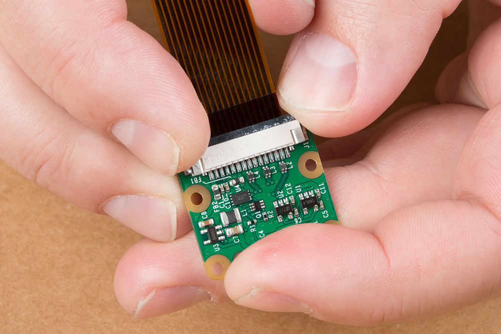
Now you can mount the Raspberry Pi Camera to the pan-tilt mechanism. Make sure the correct side is facing up. Once mounted, it should look something like what we see here:
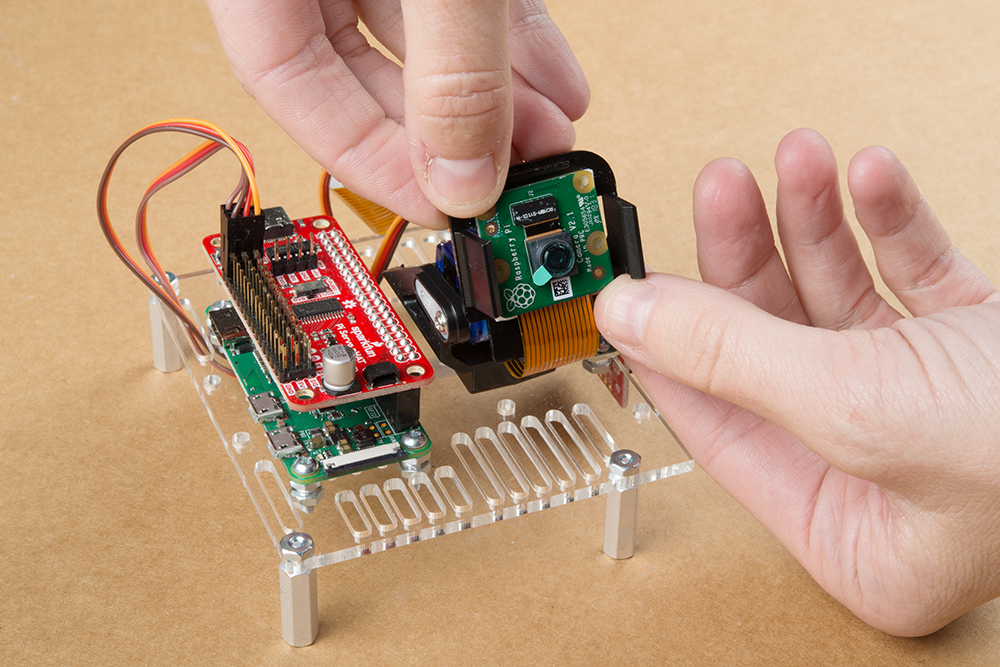
You'll also need to connect the camera ribbon cable to the Pi Zero W. The locking mechanism for the cable is exactly the same as you saw above. Make sure the pads point upward as you see here:
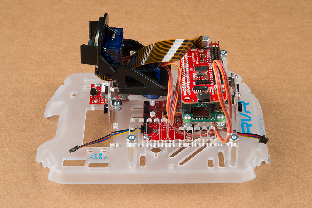
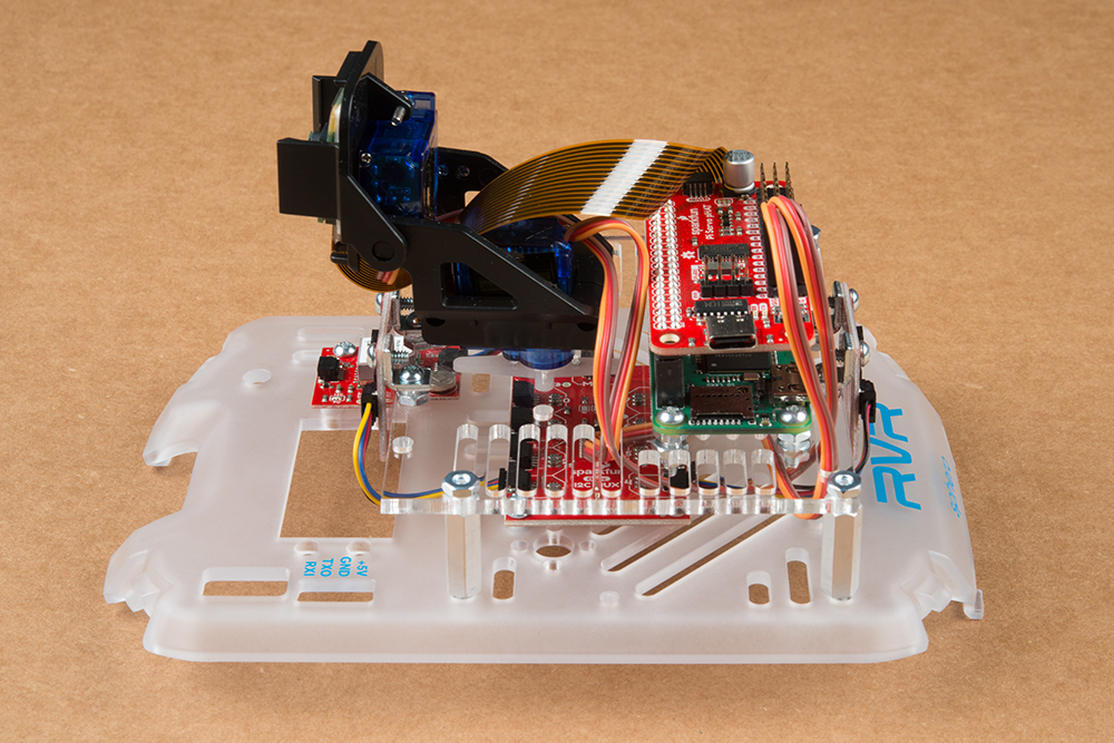
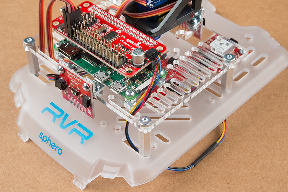
The Servo pHAT is the interface for both the pan-tilt rig and the Qwiic sensors. The pHAT plugs in so that it's stacked directly above the Pi Zero.
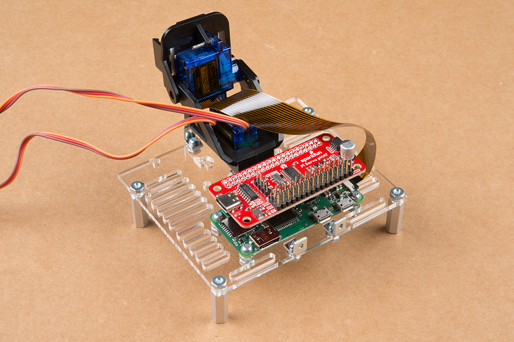
The servo cables for the pan-tilt rig will run underneath the mounting plate, under the board and pop out on the opposite side. The bottom servo plugs into ROW 0 and the top servo into ROW 1.
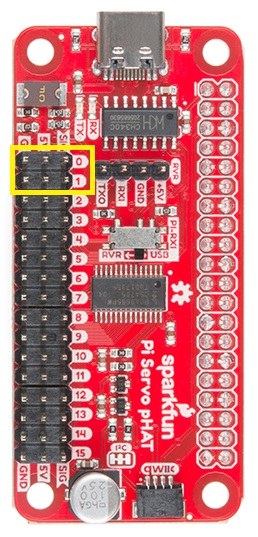
The brown wires should be on the pins closest to GPS board. See the image below.
The Qwiic cable that connects the GPS Board to the Servo pHAT through the time of flight sensor becomes obscured by the cover plate. It’s best to plug in the 50mm Qwiic cable to the GPS Board Qwiic connector facing the center of the cover plate at this point (don't plug it into the time of flight sensor quite yet).
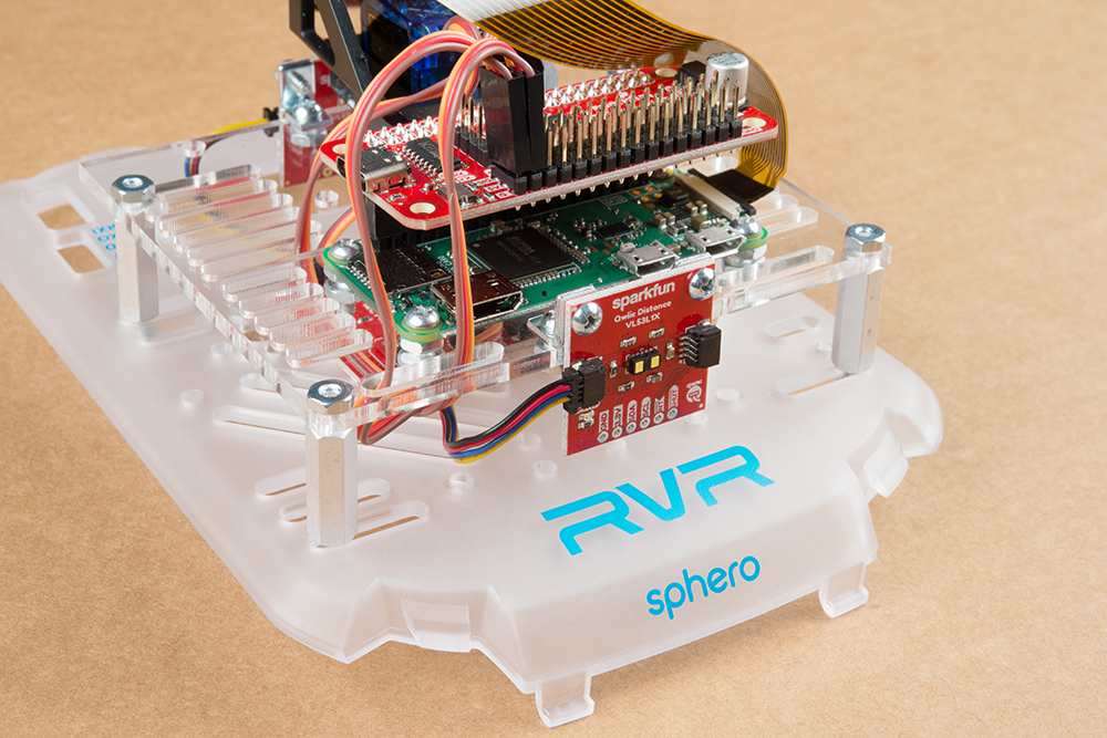
Next, we'll mount the time of flight sensors to the mounting plate. The holes from the metal bracket should line up with the holes on the top of the board as to not interfere with the pan-tilt mechanism. It should look like this:
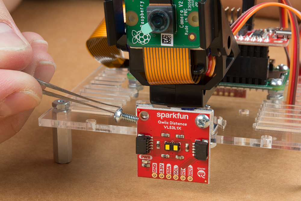
Take four of the remaining 1/4 inch screws and fasten the mounting plate to the cover plate of the RVR. The holes should lineup like this from below the cover plate:
Again, be mindful with how tight you make the screws so as to not crack the acrylic plates.
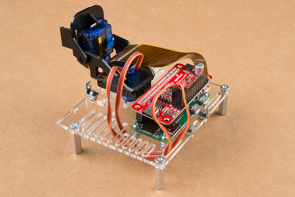
With all the boards in place, we can plug in the remaining boards to the Qwiic bus. The two 50mm Qwiic cables connected to connectors 3 and 4 on the Mux board will plug into the front and rear facing Time of Flights sensors (respectively).
Finally, we'll plug the GPS board into the Servo pHAT. Take the 200mm Qwiic cable and plug it into the Qwiic connector on the Servo pHAT. Then, we'll run the cable through the slot in the mouting plate, then down through the slot directly underneath it in the RVR Cover Plate.
Next, we'll run the cable back up through the outside slot next to the GPS board mentioned in the first steps. Plug the cable into the Qwiic connector on the GPS board facing forward.
We'll take any slack from the 200mm cable and pull it gently under the RVR Cover Plate giving the system a cleaner look from the visible side.

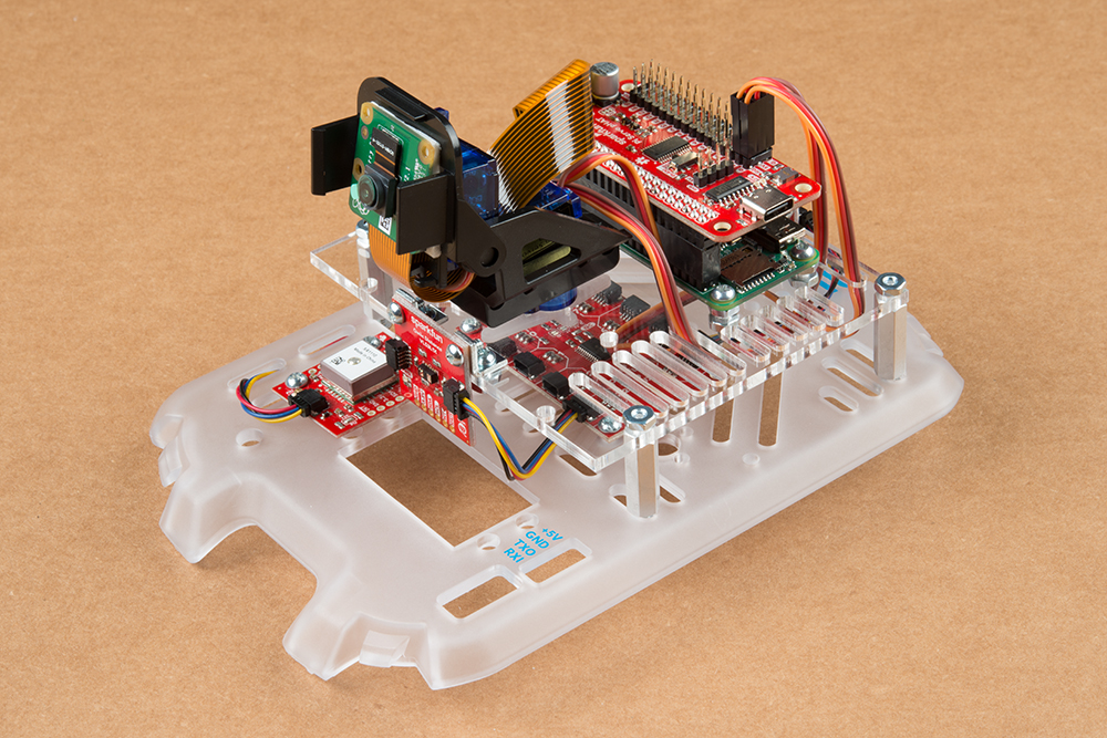
Congratulations! You've built the entire system. Now it's time to connect it to the RVR. Gently clip the RVR Cover Plate into place.
In the final step we'll then connect the 4 pin Ribbon Cable from the four pin connector on the Servo pHAT to the UART Connector on the RVR.
To keep the UART cable from obscuring the view for the pan-tilt camera, I run it under the mounting plate. Refer to the images below - feel free to click on an image to see it more closely!
") |
 |
| Cable outside the mounting plate | Cable run under the mounting plate |
Congratulations! You've completed the kit and are ready to start coding!
So you've got this amazing looking robot. Now what? Time to program it!
Head on over to the Getting Started with the Autonomous Kit for the Sphero RVR Tutorial to get coding.
Need more information on the components included in this kit? We've got it!
Need more inspiration? Check out some of these other great SparkFun tutorials!
learn.sparkfun.com | CC BY-SA 3.0 | SparkFun Electronics | Niwot, Colorado
