Addressable LED Neon Flex Rope Hookup Guide
Introduction
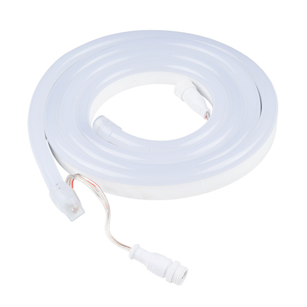
The addressable LED Neon Flex Rope adds cool lighting effects for outdoor and indoor uses including in hallways and stairs, holiday lighting and more! In this hookup guide, you will learn how to connect, power, and control the LED segments with an Arduino.
LED Neon Flex Rope
COM-14555Required Materials
To follow along with this project tutorial, you will need the following materials. You may not need everything though depending on what you have. Add it to your cart, read through the guide, and adjust the cart as necessary. If you are just looking at powering up the LED neon flex rope and using its demo mode, you will need the following.
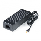
Power Supply - 24V (5A)
TOL-13758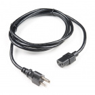
Power Cable - 10A IEC C13 - 2m
TOL-14935To test and control the segments, you will need the following materials listed below.
Tools
Depending on the application, you may need a soldering iron, solder, and general soldering accessories for a more secure connection. Otherwise, the following tools will suffice for hooking up and testing.
Suggested Reading
If you aren't familiar with the following concepts, we recommend checking out these tutorials before continuing.
What is an Arduino?
Installing Arduino IDE
Hardware Overview
The LED Neon Flex Rope uses the UCS1903 chipset and LEDs. The electronics are sealed in a waterproof IP65 silicone housing and diffuses the light emitting from the LEDs.
Pinout
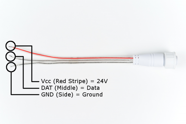
To power or control the LED neon flex rope, you will need to connect to the female bare wire connector. 24V is required to power the LED Neon flex rope using the wire with the red stripe. The center wire is the data pin when using with a microcontroller. The third wire on the other side is for ground.
Below lists a hookup table of the pinout for reference.
| LED Neon Flex Rope | Pinout |
|---|---|
| Vcc (Red Striped) | 24V |
| DAT (Middle) | Data |
| GND (Side) | Ground |
LED Strip Segments
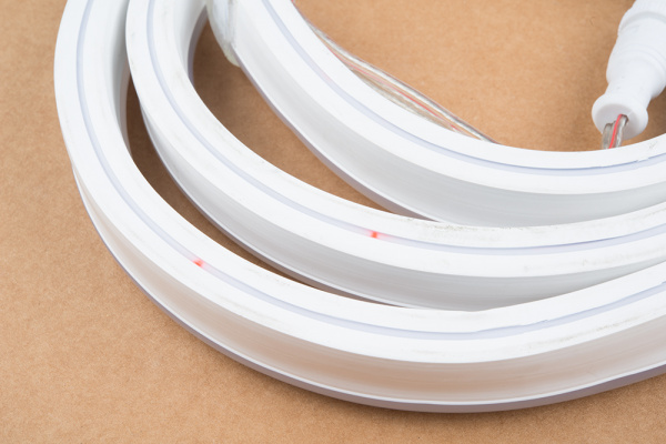
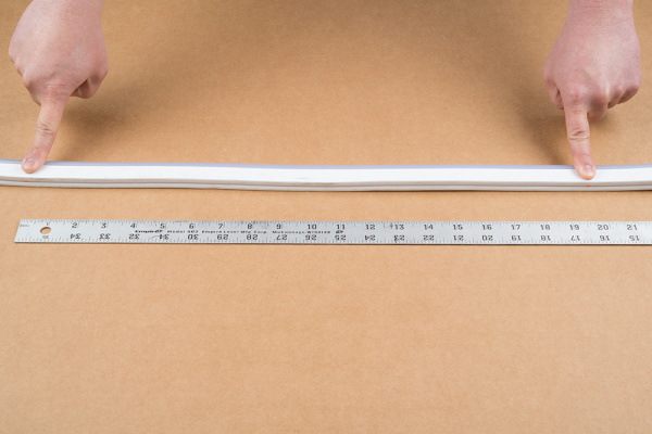
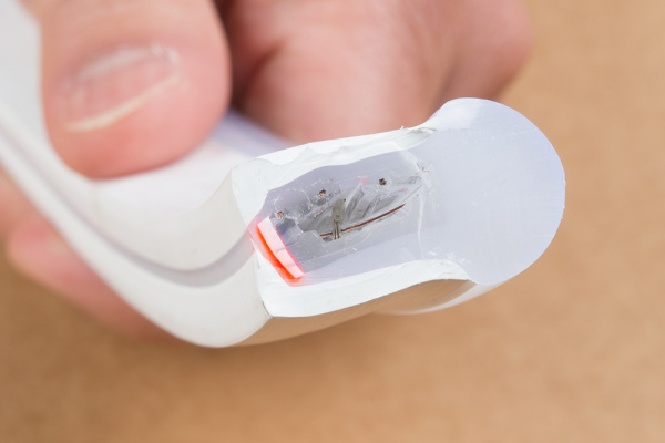
For those interested in cutting the LED neon flex rope down, you can reduce the length with the help of the colored markers on the bottom of the housing. The markers are guides and are not exact locations between the LED segments.
Each LED strip segment is about 20 inches long.
Each segment uses wires to connect between each LED strip that is sealed in the housing.
 |
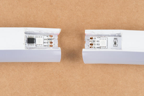 |
| Closeup Side View of a Cut LED Neon Flex Rope | Teardown of the LED Neon Flex Rope |
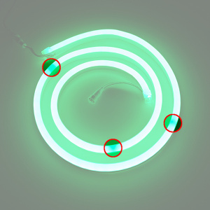
Once you determine the location of the wires connecting the LED segments, you can completely cut through the LED neon flex rope. Make sure that the LED strip is not powered when adjusting the length.
If you decide to cut the strip down, make sure to seal the exposed circuit with some epoxy or hot glue.
Hardware Hookup w/ Power Only
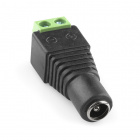
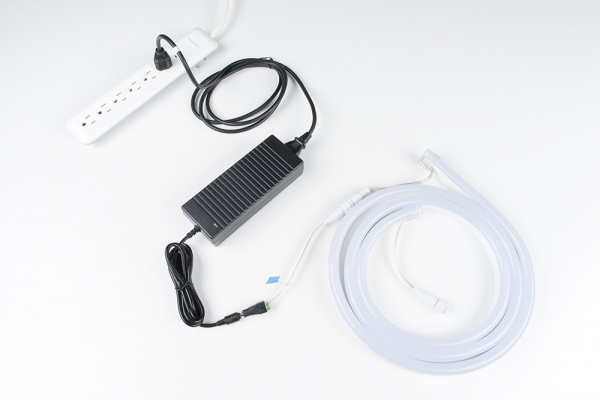
When powering the LED neon flex rope with only power, it will display a demo. Insert the 3-prong power cable into the 24V power supply. Then make the following connections with using a female DC barrel jack adapter.
| 24V Power Supply | Female DC Barrel Jack Adapter | LED Neon Flex Rope Pinout |
|---|---|---|
| Center Positive | + | Vcc (Red Striped) = 24V |
| Clear (Middle) = DAT | ||
| GND | - | Clear (Side) = GND |
Once connected, insert and fasten the adapter to the female bare wire connector into the LED neon flex rope. The setup should look like the image below. Tape was used to insulate the DAT pin since the wire was exposed.
Demo Mode
By connecting only to the power pins, the LED Neon Flex Rope will run a demo mode. This can include the rope cycling colors using different patterns. This can include:
- one solid color
- pulse and fade
- alternating between colors
- each segment incrementally lighting up with one color
Hardware Hookup w/ Arduino
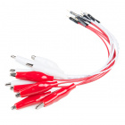
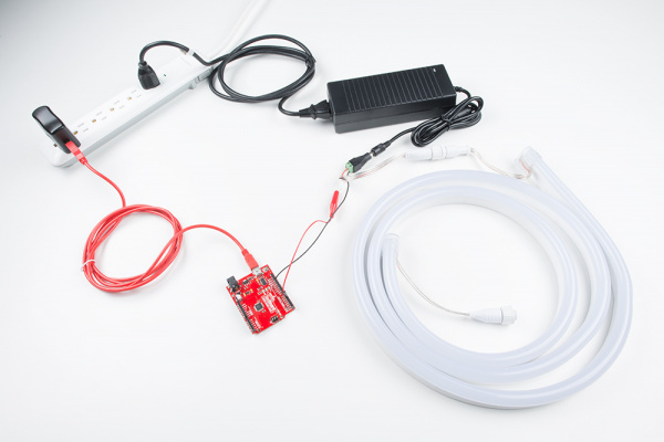
For users that want to control the animations or react to input from a sensor, an Arduino microcontroller can be used to control the LED neon flex rope's segments. For a quick connection, we will use an alligator clip with pigtail and hookup wire.
Connecting to the DAT Pin
For initial testing, we will be using an alligator clip with pigtail to connect the LED Neon flex's DAT pin to the software defined control pin on the Arduino. Use the alligator clip to clamp on the DAT pin wire and then connect the other end to D5.
Additional Power Supply and GND Reference
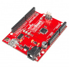
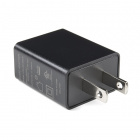
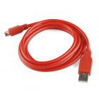
Since the recommended input voltage via the barrel jack for the RedBoard is 15V, an additional power supply is required. For the scope of this tutorial, we will use the mini-USB connector on the Arduino to power the control circuit with 5V. A 5V USB port from a computer can be used during testing. A 5V USB wall adapter can be used when powering the Arduino in a project or installation.
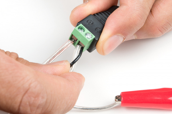
Since we are adding an additional power supply, make sure to ground the LED neon flex rope with the control circuit. Strip a piece of wire. Then connect the "-" on the DC barrel jack adapter to the Arduino's GND pin. Wrap the wires together to make a more secure connection.
 |
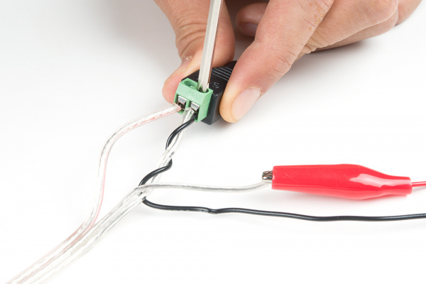 |
| Insert Wire to GND for Reference | Screw In GND Wires |
Hookup Table
Based on the connections described above, here is a hookup table of the connections.
| 24V Power Supply | Female DC Barrel Jack Adapter | LED Neon Flex Rope Pinout | Arduino | 5V Power Supply |
|---|---|---|---|---|
| Center Positive | + | Vcc (Red striped) = 24V | ||
| 5V | 5V | |||
| Clear (middle wire) = DAT | Pin 5 (or whatever is defined) | |||
| GND | - | Clear (side) = GND | GND | GND |
The final circuit should look similar to the image below.
Library Overview
Note: This example assumes you are using the latest version of the Arduino IDE on your desktop. If this is your first time using Arduino, please review our tutorial on installing the Arduino IDE. If you have not previously installed an Arduino library, please check out our installation guide.
To control the LED Neon Flex Rope, you could use a 5V Arduino-based microcontroller. You will need to download and install Daniel Garcia’s FastLED library using the library manager. You can also manually install it from the GitHub Repository by downloading the library from the button below.
Parameters
When using the FastLED library, certain parameters need to be adjusted to be compatible with the chipset. When using the FastLED library, the LED_TYPE would be defined as the UCS1903 chipset. There are 16 segments per LED Neon Flex Rope to control so the NUM_LEDs is 16. The COLOR_ORDER is BRG so:
red = blue
green = red
blue = green
Example Code
The FastLED library includes a few examples for a variety of addressable LED chipsets to get started. The following examples will demonstrate how to modify the example to use with the UCS1903 chipset. For more information, check out the FastLED Library's wiki.
FastLED Blink Modification
For simplicity, lets blink one segment of one LED neon flex rope using the FastLED's Blink.ino example by following the steps listed below:
- First adjust the number of LEDs in the strip to 16.
- Change the
DATA_PINto pin 5. - Comment out the
CLOCK_PINand LED arrangement for theneopixel. - Uncomment out the LED arrangement for the
UCS1903chipset. - Modify the color order by changing
RGBtoBRG.
Or copy and paste the modified example in an Arduino sketch. After uploading, you should see one segment blink with red.
language:c
/*Modified FastLED Blink.ino Example
 *
 * Description: This modified example is used to control one segment
     * of the LED Neon Flex Rope.
 */
#include "FastLED.h"

// How many leds in your strip?
#define NUM_LEDS 16 //# of segments on the LED Neon Flex Rope

// For led chips like Neopixels, which have a data line, ground, and power, you just
// need to define DATA_PIN.  For led chipsets that are SPI based (four wires - data, clock,
// ground, and power), like the LPD8806 define both DATA_PIN and CLOCK_PIN
#define DATA_PIN 5
//#define CLOCK_PIN 13

// Define the array of leds
CRGB leds[NUM_LEDS];

void setup() {
      // Uncomment/edit one of the following lines for your leds arrangement.
      // FastLED.addLeds<TM1803, DATA_PIN, RGB>(leds, NUM_LEDS);
      // FastLED.addLeds<TM1804, DATA_PIN, RGB>(leds, NUM_LEDS);
      // FastLED.addLeds<TM1809, DATA_PIN, RGB>(leds, NUM_LEDS);
      // FastLED.addLeds<WS2811, DATA_PIN, RGB>(leds, NUM_LEDS);
      // FastLED.addLeds<WS2812, DATA_PIN, RGB>(leds, NUM_LEDS);
      // FastLED.addLeds<WS2812B, DATA_PIN, RGB>(leds, NUM_LEDS);
      //FastLED.addLeds<NEOPIXEL, DATA_PIN>(leds, NUM_LEDS);
      // FastLED.addLeds<APA104, DATA_PIN, RGB>(leds, NUM_LEDS);
      FastLED.addLeds<UCS1903, DATA_PIN, BRG>(leds, NUM_LEDS);
      // FastLED.addLeds<UCS1903B, DATA_PIN, RGB>(leds, NUM_LEDS);
      // FastLED.addLeds<GW6205, DATA_PIN, RGB>(leds, NUM_LEDS);
      // FastLED.addLeds<GW6205_400, DATA_PIN, RGB>(leds, NUM_LEDS);

      // FastLED.addLeds<WS2801, RGB>(leds, NUM_LEDS);
      // FastLED.addLeds<SM16716, RGB>(leds, NUM_LEDS);
      // FastLED.addLeds<LPD8806, RGB>(leds, NUM_LEDS);
      // FastLED.addLeds<P9813, RGB>(leds, NUM_LEDS);
      // FastLED.addLeds<APA102, RGB>(leds, NUM_LEDS);
      // FastLED.addLeds<DOTSTAR, RGB>(leds, NUM_LEDS);

      // FastLED.addLeds<WS2801, DATA_PIN, CLOCK_PIN, RGB>(leds, NUM_LEDS);
      // FastLED.addLeds<SM16716, DATA_PIN, CLOCK_PIN, RGB>(leds, NUM_LEDS);
      // FastLED.addLeds<LPD8806, DATA_PIN, CLOCK_PIN, RGB>(leds, NUM_LEDS);
      // FastLED.addLeds<P9813, DATA_PIN, CLOCK_PIN, RGB>(leds, NUM_LEDS);
      // FastLED.addLeds<APA102, DATA_PIN, CLOCK_PIN, RGB>(leds, NUM_LEDS);
      // FastLED.addLeds<DOTSTAR, DATA_PIN, CLOCK_PIN, RGB>(leds, NUM_LEDS);
}

void loop() {
  // Turn the LED on, then pause
  leds[0] = CRGB::Red;
  FastLED.show();
  delay(500);
  // Now turn the LED off, then pause
  leds[0] = CRGB::Black;
  FastLED.show();
  delay(500);
}
Blink Each Segment
To control all the segments with control, you would need to address each segment in the array with a color. Write code to address each segment defined in the array and reduce the delay between each blink. Or copy and paste the modified blink example in an Arduino sketch. After uploading, you should see each segment blink red.
language:c
/*Modified FastLED Blink.ino Example
*
* Description: This modified example is used to control all segments
* of the LED Neon Flex Rope.
*/
#include "FastLED.h"

// How many leds in your strip?
#define NUM_LEDS 16 //# of segments on the LED Neon Flex Rope

// For led chips like Neopixels, which have a data line, ground, and power, you just
// need to define DATA_PIN.  For led chipsets that are SPI based (four wires - data, clock,
// ground, and power), like the LPD8806 define both DATA_PIN and CLOCK_PIN
#define DATA_PIN 5
//#define CLOCK_PIN 13 //not used with UCS1903 chipset

// Define the array of leds
CRGB leds[NUM_LEDS];

void setup() {
    // Uncomment/edit one of the following lines for your leds arrangement.
    // FastLED.addLeds<TM1803, DATA_PIN, RGB>(leds, NUM_LEDS);
    // FastLED.addLeds<TM1804, DATA_PIN, RGB>(leds, NUM_LEDS);
    // FastLED.addLeds<TM1809, DATA_PIN, RGB>(leds, NUM_LEDS);
    // FastLED.addLeds<WS2811, DATA_PIN, RGB>(leds, NUM_LEDS);
    // FastLED.addLeds<WS2812, DATA_PIN, RGB>(leds, NUM_LEDS);
    // FastLED.addLeds<WS2812B, DATA_PIN, RGB>(leds, NUM_LEDS);
    //FastLED.addLeds<NEOPIXEL, DATA_PIN>(leds, NUM_LEDS);
    // FastLED.addLeds<APA104, DATA_PIN, RGB>(leds, NUM_LEDS);
    FastLED.addLeds<UCS1903, DATA_PIN, BRG>(leds, NUM_LEDS);
    // FastLED.addLeds<UCS1903B, DATA_PIN, RGB>(leds, NUM_LEDS);
    // FastLED.addLeds<GW6205, DATA_PIN, RGB>(leds, NUM_LEDS);
    // FastLED.addLeds<GW6205_400, DATA_PIN, RGB>(leds, NUM_LEDS);

    // FastLED.addLeds<WS2801, RGB>(leds, NUM_LEDS);
    // FastLED.addLeds<SM16716, RGB>(leds, NUM_LEDS);
    // FastLED.addLeds<LPD8806, RGB>(leds, NUM_LEDS);
    // FastLED.addLeds<P9813, RGB>(leds, NUM_LEDS);
    // FastLED.addLeds<APA102, RGB>(leds, NUM_LEDS);
    // FastLED.addLeds<DOTSTAR, RGB>(leds, NUM_LEDS);

    // FastLED.addLeds<WS2801, DATA_PIN, CLOCK_PIN, RGB>(leds, NUM_LEDS);
    // FastLED.addLeds<SM16716, DATA_PIN, CLOCK_PIN, RGB>(leds, NUM_LEDS);
    // FastLED.addLeds<LPD8806, DATA_PIN, CLOCK_PIN, RGB>(leds, NUM_LEDS);
    // FastLED.addLeds<P9813, DATA_PIN, CLOCK_PIN, RGB>(leds, NUM_LEDS);
    // FastLED.addLeds<APA102, DATA_PIN, CLOCK_PIN, RGB>(leds, NUM_LEDS);
    // FastLED.addLeds<DOTSTAR, DATA_PIN, CLOCK_PIN, RGB>(leds, NUM_LEDS);
}

void loop() {
// Turn the LED on, then pause
leds[0] = CRGB::Red;
FastLED.show();
delay(250);
// Now turn the LED off, then pause
leds[0] = CRGB::Black;
FastLED.show();
delay(250);

// Turn the LED on, then pause
leds[1] = CRGB::Red;
FastLED.show();
delay(250);
// Now turn the LED off, then pause
leds[1] = CRGB::Black;
FastLED.show();
delay(250);

// Turn the LED on, then pause
leds[2] = CRGB::Red;
FastLED.show();
delay(250);
// Now turn the LED off, then pause
leds[2] = CRGB::Black;
FastLED.show();
delay(250);

// Turn the LED on, then pause
leds[3] = CRGB::Red;
FastLED.show();
delay(250);
// Now turn the LED off, then pause
leds[3] = CRGB::Black;
FastLED.show();
delay(250);

// Turn the LED on, then pause
leds[4] = CRGB::Red;
FastLED.show();
delay(250);
// Now turn the LED off, then pause
leds[4] = CRGB::Black;
FastLED.show();
delay(250);

// Turn the LED on, then pause
leds[5] = CRGB::Red;
FastLED.show();
delay(250);
// Now turn the LED off, then pause
leds[5] = CRGB::Black;
FastLED.show();
delay(250);

// Turn the LED on, then pause
leds[6] = CRGB::Red;
FastLED.show();
delay(250);
// Now turn the LED off, then pause
leds[6] = CRGB::Black;
FastLED.show();
delay(250);


// Turn the LED on, then pause
leds[7] = CRGB::Red;
FastLED.show();
delay(250);
// Now turn the LED off, then pause
leds[7] = CRGB::Black;
FastLED.show();
delay(250);

// Turn the LED on, then pause
leds[8] = CRGB::Red;
FastLED.show();
delay(250);
// Now turn the LED off, then pause
leds[8] = CRGB::Black;
FastLED.show();
delay(250);

// Turn the LED on, then pause
leds[9] = CRGB::Red;
FastLED.show();
delay(250);
// Now turn the LED off, then pause
leds[9] = CRGB::Black;
FastLED.show();
delay(250);

// Turn the LED on, then pause
leds[10] = CRGB::Red;
FastLED.show();
delay(250);
// Now turn the LED off, then pause
leds[10] = CRGB::Black;
FastLED.show();
delay(250);

// Turn the LED on, then pause
leds[11] = CRGB::Red;
FastLED.show();
delay(250);
// Now turn the LED off, then pause
leds[11] = CRGB::Black;
FastLED.show();
delay(250);

// Turn the LED on, then pause
leds[12] = CRGB::Red;
FastLED.show();
delay(250);
// Now turn the LED off, then pause
leds[12] = CRGB::Black;
FastLED.show();
delay(250);

// Turn the LED on, then pause
leds[13] = CRGB::Red;
FastLED.show();
delay(250);
// Now turn the LED off, then pause
leds[13] = CRGB::Black;
FastLED.show();
delay(250);

// Turn the LED on, then pause
leds[14] = CRGB::Red;
FastLED.show();
delay(250);
// Now turn the LED off, then pause
leds[14] = CRGB::Black;
FastLED.show();
delay(250);

// Turn the LED on, then pause
leds[15] = CRGB::Red;
FastLED.show();
delay(250);
// Now turn the LED off, then pause
leds[15] = CRGB::Black;
FastLED.show();
delay(250);
}
Color Palette Modification
Let's try modifying one more example from the Fast LED library to add the color paltette animation to the LED Neon Flex Rope light. After uploading, you should see the patterns cycling.
language:c
/*Modified FastLED ColorPalette.ino Example
*
* Description: This modified ColorPalette example is used to control all segments
* of the LED Neon Flex Rope.
*/

#include <FastLED.h>

#define LED_PIN     5
#define NUM_LEDS    16
#define BRIGHTNESS  255
#define LED_TYPE    UCS1903
#define COLOR_ORDER BRG
CRGB leds[NUM_LEDS];

#define UPDATES_PER_SECOND 100

// This example shows several ways to set up and use 'palettes' of colors
// with FastLED.
//
// These compact palettes provide an easy way to re-colorize your
// animation on the fly, quickly, easily, and with low overhead.
//
// USING palettes is MUCH simpler in practice than in theory, so first just
// run this sketch, and watch the pretty lights as you then read through
// the code.  Although this sketch has eight (or more) different color schemes,
// the entire sketch compiles down to about 6.5K on AVR.
//
// FastLED provides a few pre-configured color palettes, and makes it
// extremely easy to make up your own color schemes with palettes.
//
// Some notes on the more abstract 'theory and practice' of
// FastLED compact palettes are at the bottom of this file.

CRGBPalette16 currentPalette;
TBlendType    currentBlending;

extern CRGBPalette16 myRedWhiteBluePalette;
extern const TProgmemPalette16 myRedWhiteBluePalette_p PROGMEM;


void setup() {
    delay( 3000 ); // power-up safety delay
    FastLED.addLeds<LED_TYPE, LED_PIN, COLOR_ORDER>(leds, NUM_LEDS).setCorrection( TypicalLEDStrip );
    FastLED.setBrightness(  BRIGHTNESS );

    currentPalette = RainbowColors_p;
    currentBlending = LINEARBLEND;
}


void loop()
{
    ChangePalettePeriodically();

    static uint8_t startIndex = 0;
    startIndex = startIndex + 1; /* motion speed */

    FillLEDsFromPaletteColors( startIndex);

    FastLED.show();
    FastLED.delay(1000 / UPDATES_PER_SECOND);
}

void FillLEDsFromPaletteColors( uint8_t colorIndex)
{
    uint8_t brightness = 255;

    for( int i = 0; i < NUM_LEDS; i++) {
        leds[i] = ColorFromPalette( currentPalette, colorIndex, brightness, currentBlending);
        colorIndex += 3;
    }
}


// There are several different palettes of colors demonstrated here.
//
// FastLED provides several 'preset' palettes: RainbowColors_p, RainbowStripeColors_p,
// OceanColors_p, CloudColors_p, LavaColors_p, ForestColors_p, and PartyColors_p.
//
// Additionally, you can manually define your own color palettes, or you can write
// code that creates color palettes on the fly.  All are shown here.

void ChangePalettePeriodically()
{
    uint8_t secondHand = (millis() / 1000) % 60;
    static uint8_t lastSecond = 99;

    if( lastSecond != secondHand) {
        lastSecond = secondHand;
        if( secondHand ==  0)  { currentPalette = RainbowColors_p;         currentBlending = LINEARBLEND; }
        if( secondHand == 10)  { currentPalette = RainbowStripeColors_p;   currentBlending = NOBLEND;  }
        if( secondHand == 15)  { currentPalette = RainbowStripeColors_p;   currentBlending = LINEARBLEND; }
        if( secondHand == 20)  { SetupPurpleAndGreenPalette();             currentBlending = LINEARBLEND; }
        if( secondHand == 25)  { SetupTotallyRandomPalette();              currentBlending = LINEARBLEND; }
        if( secondHand == 30)  { SetupBlackAndWhiteStripedPalette();       currentBlending = NOBLEND; }
        if( secondHand == 35)  { SetupBlackAndWhiteStripedPalette();       currentBlending = LINEARBLEND; }
        if( secondHand == 40)  { currentPalette = CloudColors_p;           currentBlending = LINEARBLEND; }
        if( secondHand == 45)  { currentPalette = PartyColors_p;           currentBlending = LINEARBLEND; }
        if( secondHand == 50)  { currentPalette = myRedWhiteBluePalette_p; currentBlending = NOBLEND;  }
        if( secondHand == 55)  { currentPalette = myRedWhiteBluePalette_p; currentBlending = LINEARBLEND; }
    }
}

// This function fills the palette with totally random colors.
void SetupTotallyRandomPalette()
{
    for( int i = 0; i < 16; i++) {
        currentPalette[i] = CHSV( random8(), 255, random8());
    }
}

// This function sets up a palette of black and white stripes,
// using code.  Since the palette is effectively an array of
// sixteen CRGB colors, the various fill_* functions can be used
// to set them up.
void SetupBlackAndWhiteStripedPalette()
{
    // 'black out' all 16 palette entries...
    fill_solid( currentPalette, 16, CRGB::Black);
    // and set every fourth one to white.
    currentPalette[0] = CRGB::White;
    currentPalette[4] = CRGB::White;
    currentPalette[8] = CRGB::White;
    currentPalette[12] = CRGB::White;

}

// This function sets up a palette of purple and green stripes.
void SetupPurpleAndGreenPalette()
{
    CRGB purple = CHSV( HUE_PURPLE, 255, 255);
    CRGB green  = CHSV( HUE_GREEN, 255, 255);
    CRGB black  = CRGB::Black;

    currentPalette = CRGBPalette16(
                                green,  green,  black,  black,
                                purple, purple, black,  black,
                                green,  green,  black,  black,
                                purple, purple, black,  black );
}


// This example shows how to set up a static color palette
// which is stored in PROGMEM (flash), which is almost always more
// plentiful than RAM.  A static PROGMEM palette like this
// takes up 64 bytes of flash.
const TProgmemPalette16 myRedWhiteBluePalette_p PROGMEM =
{
    CRGB::Red,
    CRGB::Gray, // 'white' is too bright compared to red and blue
    CRGB::Blue,
    CRGB::Black,

    CRGB::Red,
    CRGB::Gray,
    CRGB::Blue,
    CRGB::Black,

    CRGB::Red,
    CRGB::Red,
    CRGB::Gray,
    CRGB::Gray,
    CRGB::Blue,
    CRGB::Blue,
    CRGB::Black,
    CRGB::Black
};


// Additionl notes on FastLED compact palettes:
//
// Normally, in computer graphics, the palette (or "color lookup table")
// has 256 entries, each containing a specific 24-bit RGB color.  You can then
// index into the color palette using a simple 8-bit (one byte) value.
// A 256-entry color palette takes up 768 bytes of RAM, which on Arduino
// is quite possibly "too many" bytes.
//
// FastLED does offer traditional 256-element palettes, for setups that
// can afford the 768-byte cost in RAM.
//
// However, FastLED also offers a compact alternative.  FastLED offers
// palettes that store 16 distinct entries, but can be accessed AS IF
// they actually have 256 entries; this is accomplished by interpolating
// between the 16 explicit entries to create fifteen intermediate palette
// entries between each pair.
//
// So for example, if you set the first two explicit entries of a compact
// palette to Green (0,255,0) and Blue (0,0,255), and then retrieved
// the first sixteen entries from the virtual palette (of 256), you'd get
// Green, followed by a smooth gradient from green-to-blue, and then Blue.
More Examples!
Now that we have some experience using two of the examples, try modifying and testing out the others in the FastLED library!
Resources and Going Further
Now that you've successfully got your LED Neon Flex Rope up and running, it's time to incorporate it into your own project!
For more information, check out the resources below:
Need some inspiration for your next project? Check out some of these related tutorials:
