VEX + Arduino Control -- Best of both worlds!
Many schools and homes have VEX robotics systems. It's an awesome and amazing platform. I've casually mentioned to several friends that integrating VEX with Arduino is super simple to do... Here's a quick snap-shot at what we got working today.

There are thousands of schools using VEX in the classroom. VEX started with a simple PIC microcontroller system and recently upgraded their platform to a Cortex based system. These are fantastic, high-powered, fast systems that work well in many classrooms. There are a variety of programming environments for VEX from easyC, robotC, to ModKit and Flowol. However, there is also a fast growing population of schools using Arduino to teach basic microcontroller programming and electronics. How can we combine these two realms?
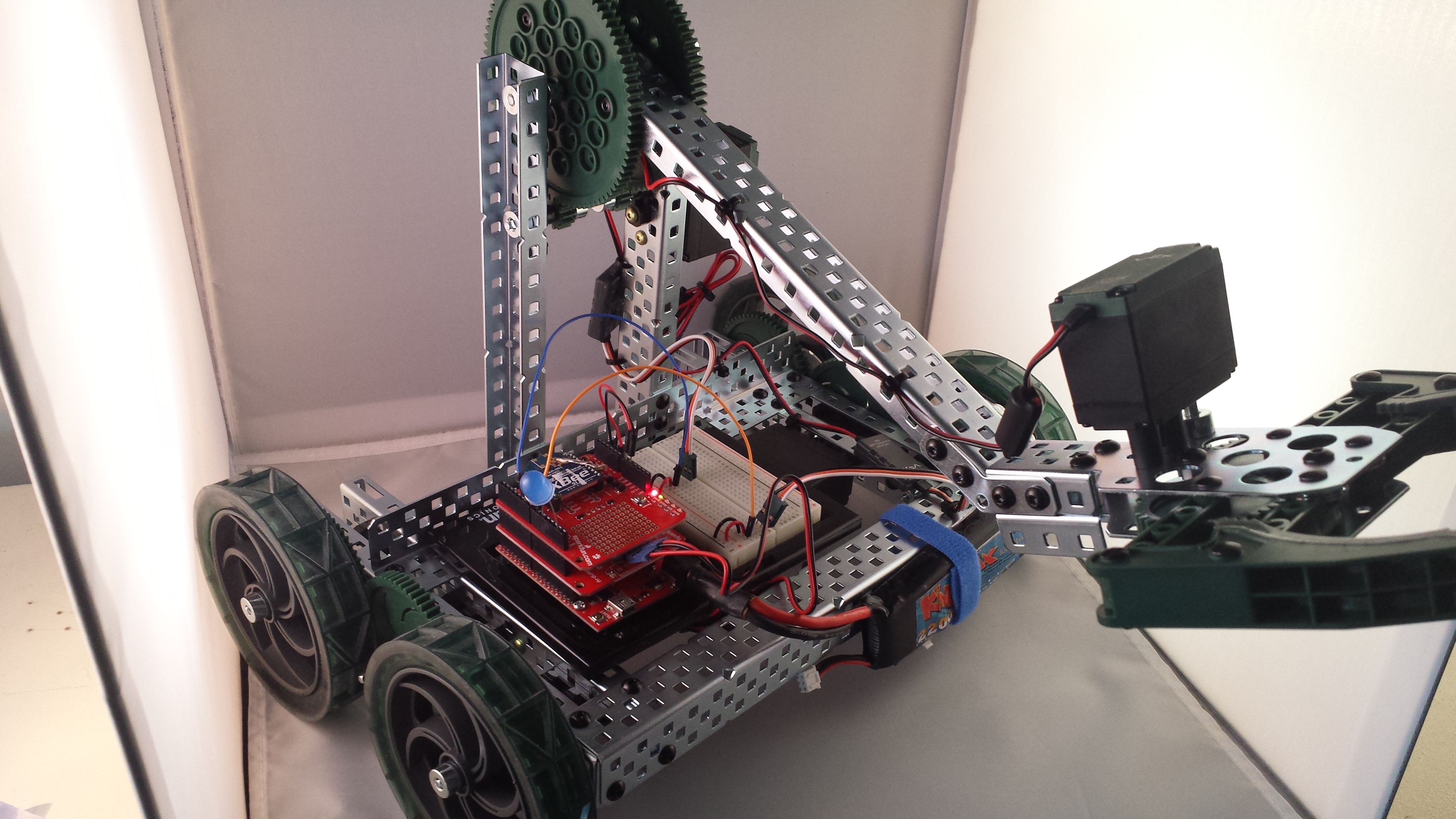
VEX has a fantastic building platform. If you are looking at expanding your robotics, mechatronics, or general structures program -- I encourage you to look into VEX. Their structural and mechanics system is fully modular and works with a minimum number of unique parts and pieces. One of the struggles I have heard from teachers is how can we integrate Arduino with what we do with VEX. Here's a quick summary of what we got working. A more in depth tutorial is in the works.
Human Control
Using Arduino as an autonomous controller for VEX motors is a pretty easy problem to solve. The bigger problem to tackle is replicating the "tele-operated" human-control that VEX provides.
VEX offers a slick WiFi Joystick control and default firmware on their Cortex controller that allows a quick "plug-and-play" experience. I wanted to re-create the same experience with as few custom parts as possible.

A quick search for USB joystcks on-line came up quite a few different options. I tried this low-cost controller, but settled with the Logitech F310 instead. It's currently availble on Amazon for $18.99 and features nearly all of the same buttons and controls as the traditional VEXnet joystick.

Hardware Used
Aside from the joystick and the Clawbot kit from VEX, here is a wishlist of all the parts I used on this build. With the battery, the total retail cost is about $200. What I really like about this solution is that it opens up the controller to all sorts of other interfaces, sensors, and peripherals that you can build and hack on.
If you want to try this, you will need to pair your XBee Radios. You can check out this tutorial if you've never done this before:
Control Programming
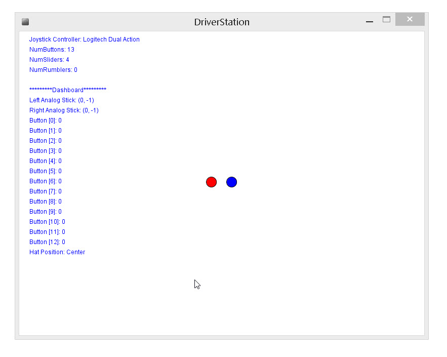
Now I had a comparable controller, I needed an interface to the Arduino. Naturally, I looked into Processing. The GameControlPlus library in Processing handles a lot of the back-end I/O for the joystick. Here is a rough DriverStation program example in Processing. You will need to install both the VSync and the GameControlPlus libraries to use this example. You can add both of these directly in Processing from the Sketch --> Add Library menu.
The code is pretty well commented. In general, what it does is interface a joystick controller and read in all of the inputs from the joystick and it sends this to the Arduino through the serial COM port associated with the XBee Radio. Alternatively, you can use a USB cable tether directly to the Arduino and for-go the wireless Xbee part - just make sure that you specify the correct COM port.
// DriverStation.pde
//
// This example uses two community supported libraries - gamecontrolplus and vsync
// you need to install both of these libraries before running this example.
//
// gamecontrolplus handles the interface with any standard USB controller
// vsync is a great library for passing data between processing and arduino
//
// Written by: B. Huang, Sparkfun Electronics --
// rev. September 12, 2014
//
import processing.serial.*;
import org.gamecontrolplus.*;
import vsync.*;

Serial myXbee;          // The serial port interface -- connected to an XBee for wireless serial to Arduino

/***************************************************************************************
// vsync objects
// Create a sender and a receiver for incoming and outgoing synchronization.
****************************************************************************************/
ValueReceiver receiver;
ValueSender sender;

// vsync public variables for passing to Arduino
public int leftX;
public int leftY;
public int rightX;
public int rightY;
public int hatPosition;

public int b0, b1, b2, b3, b4, b5, b6, b7, b8, b9, b10, b11, b12;

// variables for receiving debug data back from Arduino
public int debugVar0, debugVar1, debugVar2, debugVar3;

/***************************************************************************************
// gamecontrolplus objects
// Objects for managing and hangling interface to the joystick controller
****************************************************************************************/
ControlIO control;
ControlDevice device;

ControlButton[] button; // Array of buttons - one for each button control on joystick
ControlHat hat;         // The 'hat' is the up/down/left/right control on joystick

Stick rightStick;       // We are using a custom Stick class which combines two ControlSliders for each analog "stick"
Stick leftStick;        // each ControlSlider returns a single axis. In the constructor for the Stick object,
                        // define the X and Y ControlSlider.
int controllerID;
String controllerName;

int numDevices;         // number of 'gamecontrol' devices connected. This includes any I/O including mouse, keyboard, touchscreen...
int numButtons;         // number of buttons on joystick
int numRumblers;        // number of rumblers on joystick
int numSliders;         // number of 'sliders' or analog joystick axes

String[] hatPositionNames = {
  "Center", "Northwest", "North", "Northeast", "East", "Southeast", "South", "Southwest", "West"
};
/********************************************************
/ Misc variables for displaying text to graphics window.
/********************************************************/
int xPos = 10;
int yPos = 20;
int txtLineSpace = 20;

public class Stick {
  float x;
  float y;
  public ControlSlider sliderX;
  public ControlSlider sliderY;

  public Stick(ControlDevice controldevice, int sliderXnum, int sliderYnum) {
    sliderX = controldevice.getSlider(sliderXnum);
    sliderY = controldevice.getSlider(sliderYnum);
  }

  public float getX() {
    return sliderX.getValue();
  };

  public float getY() {
    return sliderY.getValue();
  };
}
/********************************************************
/ setup function
/********************************************************/
public void setup() {
  size(800, 600);  // Define the window size.

  // List out and setup the Serial com port interface
  print("Serial Com Ports Available: ");
  println(Serial.list());
  println();

  // myXbee = new Serial(this, "COM6", 9600);   // COM port can be specified explicitly or by index. On most PCs, it is index [0]
  myXbee = new Serial(this, Serial.list()[0], 9600);

  // Setup the gamecontrol device object
  control = ControlIO.getInstance(this);      // instantiated the controlIO object
  numDevices = control.getNumberOfDevices();  // find the number of connected controllers

  // Search for the "Joystick" controller on USB
  for (int x = 0; x < numDevices; x++) {
    println("[" + x + "] " + control.getDevice(x).getName() + " - Type: " + control.getDevice(x).getTypeName());
    if (control.getDevice(x).getTypeName() == "Stick")  // Tested using the Logitech GamePad F310
      controllerID = x;                                 // It enumerates as a type "Stick"
  }
  println();

  device = control.getDevice(controllerID);   // device object points to the joystick controller
  controllerName = device.getName();

  numButtons = device.getNumberOfButtons();
  numSliders = device.getNumberOfSliders();
  numRumblers = device.getNumberOfRumblers();

  hat = device.getHat(0); // 8 position directional control

  // define the right and left paddles on the controller.
  // Stick class combines both the up/down and left/right sliders into one object
  rightStick = new Stick(device, 1, 0); // Analog joysticks
  leftStick = new Stick(device, 3, 2);  // Analog joysticks

  button = new ControlButton[numButtons]; // creates an array of button objects for all buttons on device.
  for (int x = 0; x < numButtons; x++)
    button[x] = device.getButton(x);

  // setup for vSync control. Receiver object takes in data from Arduino. Sender object sends data to Arduino
  // the number of objects and the order of these must match between Processing and Arduino.
  receiver = new ValueReceiver(this, myXbee).observe("debugVar0").observe("debugVar1").observe("debugVar2").observe("debugVar3");
  sender = new ValueSender(this, myXbee).observe("hatPosition").observe("leftX").observe("leftY").observe("rightX").observe("rightY").observe("b0").observe("b1").observe("b2").observe("b3").observe("b4").observe("b5").observe("b6").observe("b7").observe("b8").observe("b9").observe("b10").observe("b11").observe("b12");
}

/********************************************************
/ draw function
/********************************************************/

public void draw() {
  xPos = 20;  // starting text position
  yPos = 20;
  refreshLocalVariables();  // fetches the state of the button presses and joystick to local Variables -- used with vSync Library
  background(255);
  fill(255, 0, 0); // red for LEFT stick (slider)

  ellipse(map(leftStick.getX(), -1, 1, 20, 780) - 20, map(leftStick.getY(), -1, 1, 0, 600), 20, 20);

  fill(0, 0, 255); // blue for RIGHT stick (slider)
  ellipse(map(rightStick.getX(), -1, 1, 20, 780) + 20, map(rightStick.getY(), -1, 1, 0, 600), 20, 20);

  text("Joystick Controller: " + device.getName(), xPos, yPos);
  yPos += txtLineSpace;
  text("NumButtons: " + numButtons, xPos, yPos);
  yPos += txtLineSpace;
  text("NumSliders: " + numSliders, xPos, yPos);
  yPos += txtLineSpace;
  text("NumRumblers: " + numRumblers, xPos, yPos);
  yPos += 2*txtLineSpace; // double-space

  text("*********Dashboard*********", xPos, yPos);
  yPos += txtLineSpace;
  text("Left Analog Stick: (" + leftX + ", " + leftY + ")", xPos, yPos);
  yPos += txtLineSpace;
  text("Right Analog Stick: (" + rightX + ", " + rightY + ")", xPos, yPos);
  yPos += txtLineSpace;

  for (int x = 0; x < numButtons; x++) {
    text("Button [" + x + "]: " + (int)(button[x].pressed() ? 1 : 0), xPos, yPos);
    yPos += txtLineSpace;
  }

  text("Hat Position: " + hatPositionNames[hatPosition], xPos, yPos);
  yPos += 20;
}

void refreshLocalVariables()
{
  // type casts the boolean .pressed() to an integer type.
  b0 = button[0].pressed() ? 1 : 0;
  b1 = button[1].pressed() ? 1 : 0;
  b2 = button[2].pressed() ? 1 : 0;
  b3 = button[3].pressed() ? 1 : 0;
  b4 = button[4].pressed() ? 1 : 0;
  b5 = button[5].pressed() ? 1 : 0;
  b6 = button[6].pressed() ? 1 : 0;
  b7 = button[7].pressed() ? 1 : 0;
  b8 = button[8].pressed() ? 1 : 0;
  b9 = button[9].pressed() ? 1 : 0;
  b10 = button[10].pressed() ? 1 : 0;
  b11 = button[11].pressed() ? 1 : 0;
  b12 = button[12].pressed() ? 1 : 0;

  // scales the -1 to +1 state of the slider to -255 to +255
  leftX = (int) map(leftStick.getX(), -1, 1, -255, 255);
  leftY = (int) map(leftStick.getY(), -1, 1, -255, 255);

  rightX = (int) map(rightStick.getX(), -1, 1, -255, 255);
  rightY = (int) map(rightStick.getY(), -1, 1, -255, 255);

  hatPosition = hat.getPos();
}
Right click here and select file save-as to download this code.
Arduino Code
I learned a few things as I wrote this example. Interfacing the H-Bridge controller on the ArduMoto Shield was easy. The ArduMoto Shield is perfect for driving and controlling the VEX motors. However, the ArduMoto Shield only has two channels. Additional motors require an external motor controller. Thankfully, VEX includes these in their Clawbot kit. The VEX Motor Controller 29 has a small PIC microcontroller embedded inside it. It responds to a 50 Hz pulse-width modulation (PWM) signal with a pulse width that varies from 1000 uS to 2000 uS. 1000 uS corresponds to full speed reverse and 2000 uS corresponds to full speed forward. 1500 uS, logically, causes the motor to stop.
Using the Servo library, I wrote a small function vexMotorWrite(Servo motorObj, int speed) that scales a speed value (-255 to +255) to a Servo pulse from 1000 uS to 2000 uS. You must pass this function the Servo motorObject tied to the VEX Motor Controller.
What's next?
Look for an in-depth tutorial around this. A lot of tips around using Xbees, the Servo library, and integrating all of these things together. In the meantime, let us know if you end up trying this in your own class! Happy hacking!


This is a great project. I had a few questions: Does this require that the Logitech controller be connected via USB to a laptop? Why are two Xbee explorers required? You mentioned a possible tutorial: is there any further documentation you could refer folks to?
The premise of the operation is this: * joystick controller is connected to your computer & your computer transmits wireless to the redboard arduino with an XBee * the redboard arduino receives the wireless signal through XBee * the signals received control the motors.
This uses a few libraries that I describe in the blog post -- unfortunately, I haven't written this up more formally. This blog continues to get a lot of traffic and views. I probably should write this up! :) Will definitely let everyone know as soon as it's completed.
Me and my team are working with the same bot(for a senior project) and setup as the photo above. Except we don't have the blue XBEE on top. For now we have the bot connected my laptop for power and have the Aduino command input up for putting in codes. We were wondering were we can download or copy the library code VSync.h for our bot?
The VSync library is available here on github: https://github.com/erniejunior/VSync. There are easier ways to implement this, but at the time VSync appeared to be one of the easier ways. Best of luck with your project!
Hi, I am a student who is working on an autonomous car project on my own. I am planing to put a H-bridge for the connection with motors and Arduino. However, on the photo shows on this page, you seems wired the motor with Arduino directly. Would the Arduino able to support the power of motors?
Hello!
If you use the Motor Controller 29, you can wire these directly up to the Arduino without an extra H-Bridge. The 3-wire Motor Controller 29 is essentially a built-in speed controller. It takes a PWM signal from the Arduino and then controls the motor's speed & direction based on this value.
If you're going to do this directly without the Motor Controller 29, then you'll need an H-Bridge. The Arduino can only source about 40 mA from any one of its pins. Motors need a LOT more than that. I hope that helps! Best of luck with your project.
I am teaching a robotics class and really excited to pair the vex clawbot kit with the arduino kits that my students have been learning to use. I found the basic info to do this on your site, purchased all the parts to make the vex/arduino interface work and am hoping to find a tutorial for hookup. Please let me know if there is anything out there to help put this together.
Hi #882435 -
The full documentation still needs to be cleaned up, but I'm happy to help you with your class. Please let me know if you get stuck. I have had a few other teachers implement this using the sample code provided here. Feel free to email me directly at: brian[at]sparkfun.com