What's the difference between the ZED-F9P and the ZED-X20P?
Hardware Changes
With the exclusions of the added JST connector and adjusted location of the BlueSMiRF header; the overall board dimensions, edge connectors and screw-hole locations, and PTH pin layout are exactly the same.
Antenna Connection
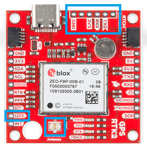
Connector Options
With the ZED-F9P we released two different boards with either a U.FL connector or an SMA connector to attach a GNSS antenna. With the ZED-X20P, we have released a single board with both options with a jumper to select the connector to be used.
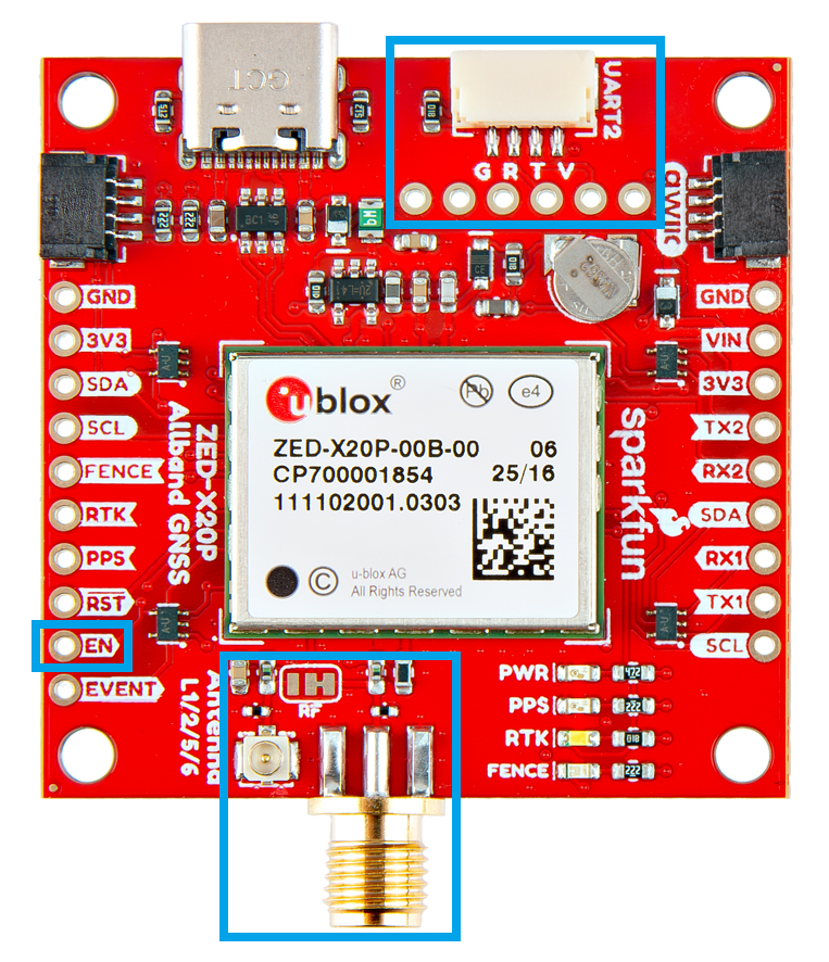
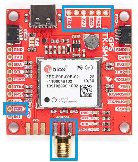
SMA: The location of the SMA connector remains the same.
U.FL: The U.FL connector’s location is slightly different by a couple millimeters. There was a hole in the board to pass a U.FL cable through.
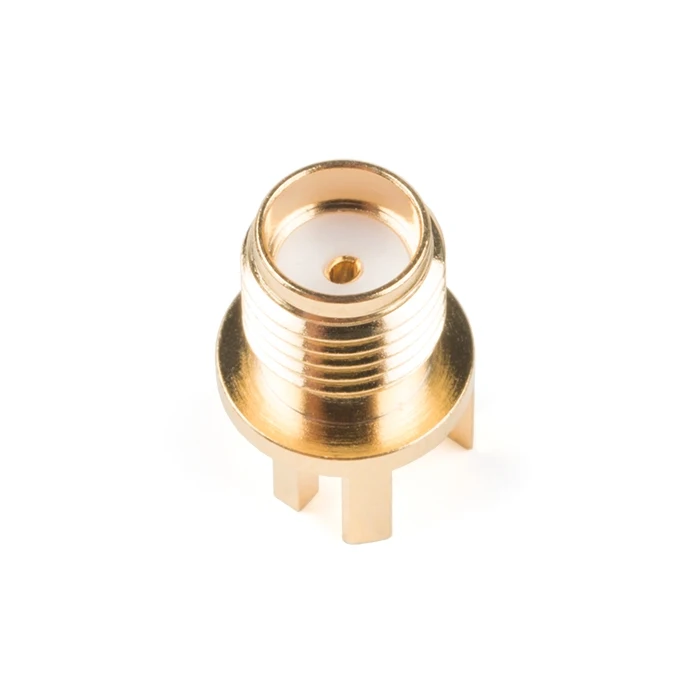
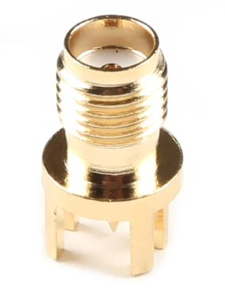
Length of SMA Connector
We recently changed suppliers for our SMA connector, so users will eventually see a slightly longer SMA connector on future boards.
BlueSMiRF Header Location
On the ZED-F9P boards, the BlueSMiRF PTH pins were located at the edge of the board. For the ZED-X20P, we have added a locking JST connector, in its place, to allow users to easily attach an RF transceiver. Therefore, the BlueSMiRF header was relocated to the interior of the board.
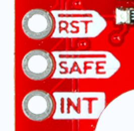
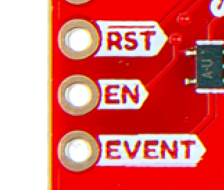
Pin Functionality
Most of the pin functionality remains the same, with the exception of a single pin. The safeboot pin on the ZED-Z20P board was relocated to a test point and replaced with the enable pin for the RT9080 LDO.
UART Interface
Baud rate:
- ZED-F9P: 9600-921600 bps
- ZED-X20P: 4800-8000000 bps
SPI Interface
Max transfer rate:
- ZED-F9P: 125 kB/s
- ZED-X20P: 880-950 kB/s
Max clock speed:
- ZED-F9P: 5.5 MHz
- ZED-X20P: 7.25-12.8 MHz
I2C Interface
The ZED-F9P only supported I2C fast-mode; while the ZED-X20P supports standard mode, fast mode, and fast mode plus.
Max bit rate:
- ZED-F9P: 400 kbit/s
- ZED-X20P: 1000 kbit/s
USB Interface
While both boards provide a USB-C connection to the GNSS receiver, on the ZED-X20P we would advise users not to rely on this interface in their designs.