VKey Voltage Keypad Hookup Guide
This Tutorial is Retired!
This tutorial covers concepts or technologies that are no longer current. It's still here for you to read and enjoy, but may not be as useful as our newest tutorials.
 Byron J.
Board Overview
Looking at the front of the board, we see an 3 by 4 array of tactile switches and three connection pads near the bottom edge of the board.
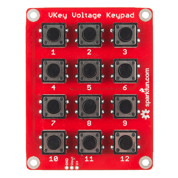
The connection pads are as follows.
GND should be connected to the ground of the host circuit.
Vout is the analog output of the keypad, and should be connected to an analog-to-digital channel (such as A0, A1, etc on an Arduino).
V+ is the power supply, and should be connected to a voltage between 3.3V - 5.5V.
How It Works
Take a look at the back of the VKey.
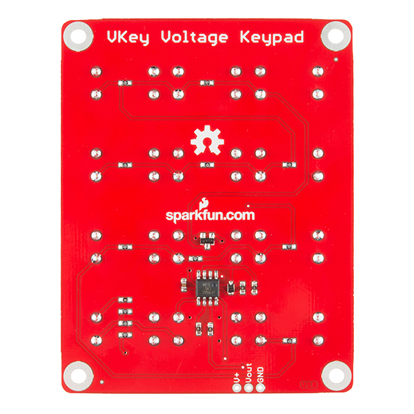
The IC is a dual opamp, used as a current source and buffer amplifier. The current source drives a string of resistors that form a voltage divider, and the tact switches select voltages at the different taps of the divider.
See the resources section for links to a much more detailed guide to the internals of the VKey.
Each of the buttons on the VKey produces a unique analog voltage, as listed below/
| Key Number | Vout (5V supply) | Vout (3.3V supply) |
| None | .057 | .053 |
| 12 | .198 | .194 |
| 11 | .396 | .388 |
| 10 | .596 | .583 |
| 9 | .794 | .776 |
| 8 | .992 | .970 |
| 7 | 1.190 | 1.164 |
| 6 | 1.388 | 1.358 |
| 5 | 1.585 | 1.551 |
| 4 | 1.781 | 1.744 |
| 3 | 1.979 | 1.938 |
| 2 | 2.176 | 2.131 |
| 1 | 2.372 | 2.323 |
As you can see, with a 5V supply, each successive button adds about 200 mV to the output voltage -- at 3.3V the voltage per step is slightly less.
One situation to consider is when more than one key is pressed at the same time. The VKey implements high-key number (or low voltage) priority -- when more than one of the switches is closed at a time, the output will indicate the higher key number. For instance, if you hold down 5 and 9 together, the output will indicate key 9 is pressed.