Using AT&T's M2X With the CC3000
This Tutorial is Retired!
This tutorial covers concepts or technologies that are no longer current. It's still here for you to read and enjoy, but may not be as useful as our newest tutorials.
 Shawn Hymel
Introduction
M2X is AT&T's Machine-to-Machine (M2M) cloud solution. You can set up any number of "streams" on https://m2x.att.com/ and post, fetch, delete data from any number of Internet-connected devices.
Great, but what does all that mean? Well, let's say you have a sensor (temperature, pressure, carbon monoxide, wind speed, etc.), and you want to log all that data to somewhere on the Internet. M2X allows you to post that sensor data and view that data from any computer or smart phone connected to the Internet.
Conversely, we can control a device connected to M2X from anywhere (as long as we have Internet access). While M2X is not explicitly set up to push data to connected devices, we can write a program for the device that polls an M2X stream for data and performs some action based on that data.
All of this falls under the umbrella of Internet of Things (IOT), in which Internet-connected embedded systems can communicate with Internet services, such as web sites or other connected devices.
In this tutorial, we use a SparkFun RedBoard (an Arduino Uno R3 will work, as well) and a CC3000 Shield to connect to M2X via WiFi. A temperature sensor, level shifter, LED, and resistor will also be needed for the tutorials. The specific components will be covered in each section.
We show how to set up an M2X account, create a stream, post sensor data to that stream, and control an LED from a stream. Keep in mind that these are just starting points for projects; if you want to monitor your oven or control your refrigerator, go for it!
Note: At the time of this tutorial's publication, M2X is still in beta form. You may find some bugs along the way. Feel free to ask questions or post bugs on the M2X Forums. Also, expect things to change as AT&T improves the M2X service.
Suggested Reading
M2X Setup
In order to use the M2X streams, we need to set up an AT&T M2X account.
Navigate to m2x.att.com.

Click on the "Sign Up" button.
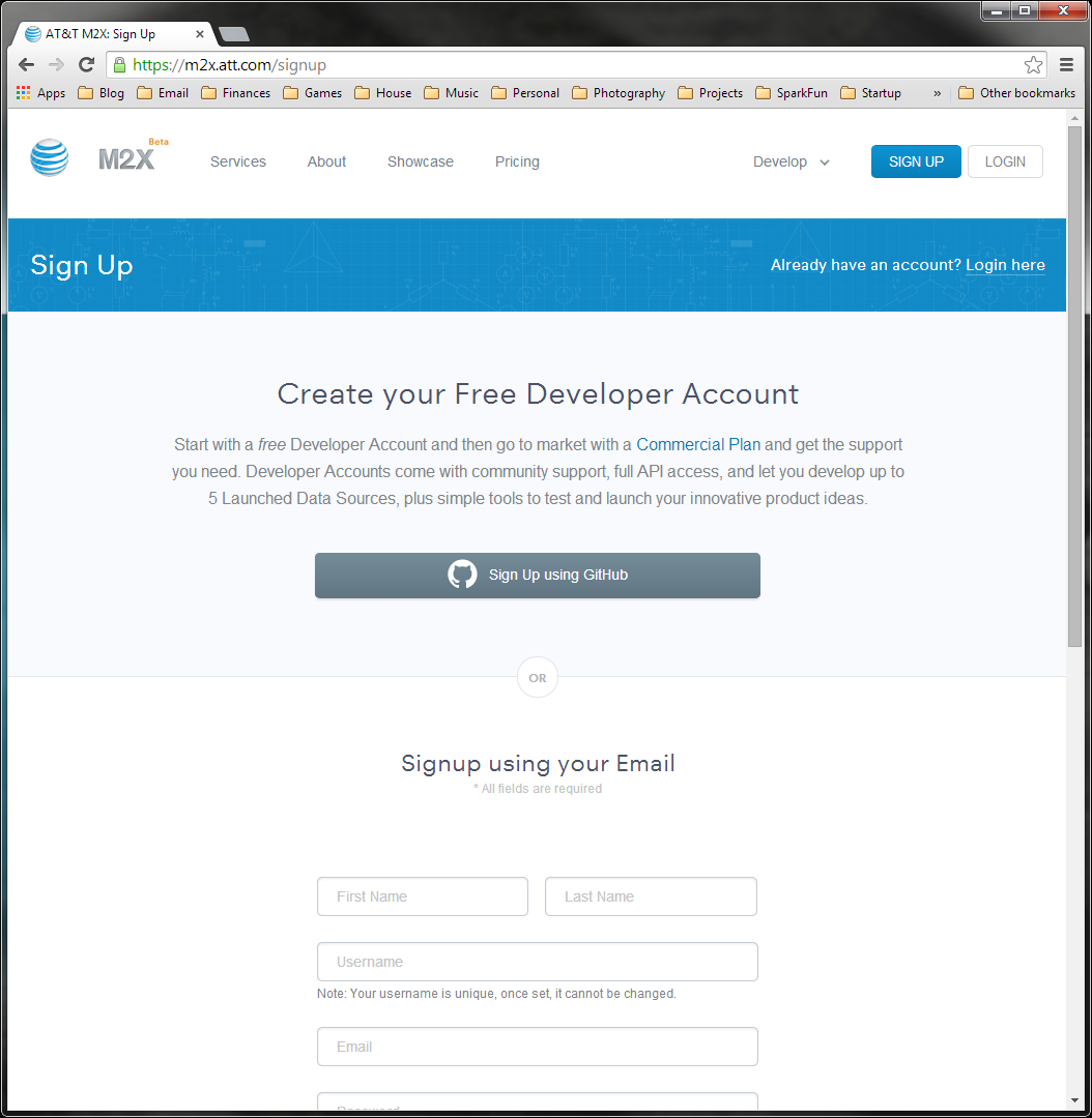
Follow the instructions on the screen to sign up for an account using your GitHub or email. If you use your email, you will need to verify your account through a link in an email from the M2X site.
Once you click on the link, you will be presented with your dashboard and a "Welcome to M2X" pop-up. Feel free to read the welcome messages or click "Skip."
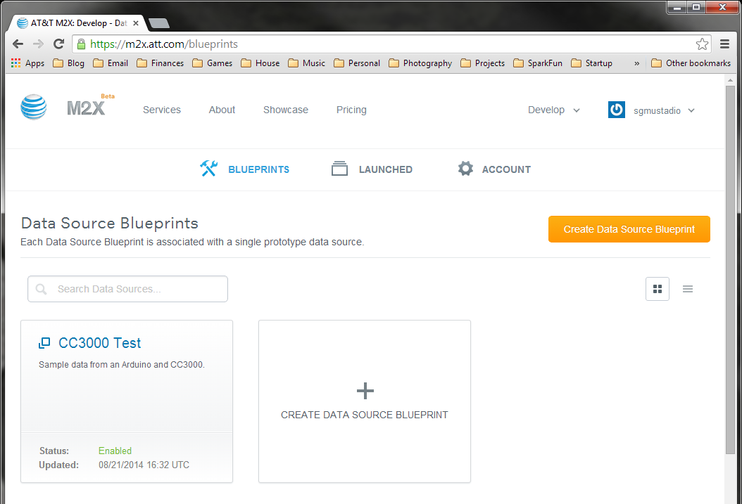
After you are done with the welcome screen, you will see your dashboard.
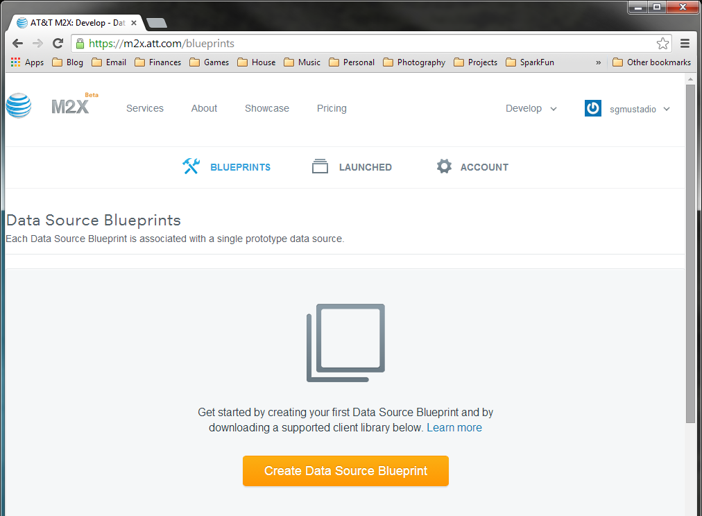
Click "Create Data Source Blueprint." Blueprints are a collection of data sources (streams) that can be multiplied and scaled to handle production data (known as a "batch").
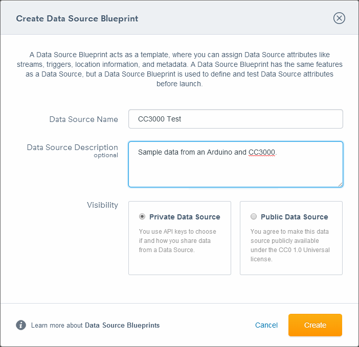
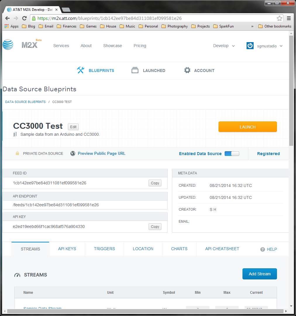
You will be asked to give your Blueprint some information. Fill out whatever you like in the Name and Description fields. For now, leave the Visibility at "Private." Click "Create." You will be presented with the dashboard for your Blueprint.
And that's it! We created a blueprint, which will hold our data streams for the tutorials. Before we can add data, we need to install a few Arduino libraries.
Install Libraries
In order to use the CC3000 and M2X with Arduino, we need to install a few libraries. Make sure you do not have the Arduino IDE open at this time.
SFE_CC3000
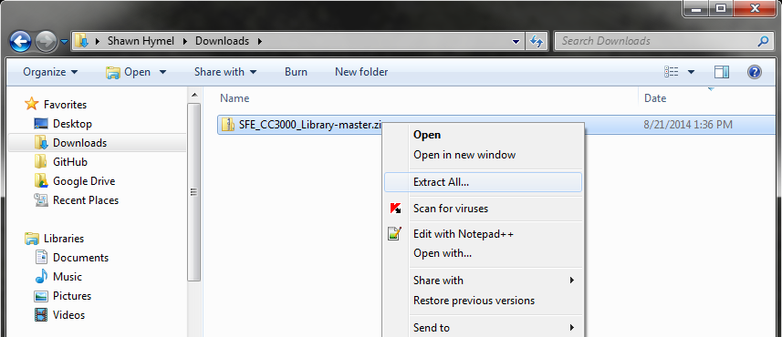
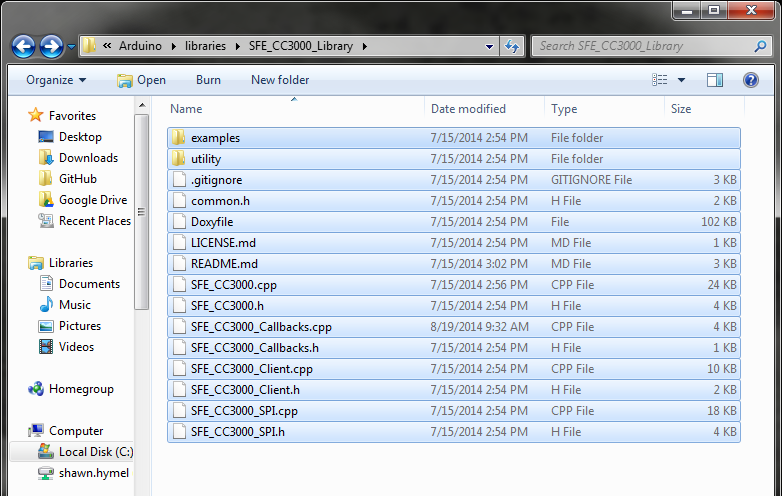
Download the SFE_CC3000_Library from GitHub: https://github.com/sparkfun/SFE_CC3000_Library. You can clone the library or download a ZIP of the whole library here.
If you downloaded the ZIP, extract the folder.
Navigate to \
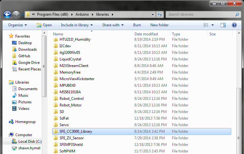
Navigate back to the downloaded library and copy all of the files inside SFE_CC3000_Library-master/SFE_CC3000_Library-master to \
jsonlite
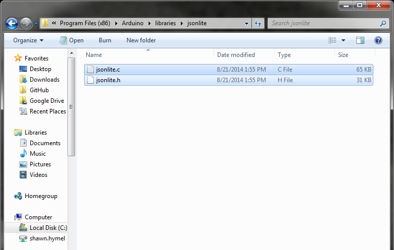
Just like we did with the CC3000 library, clone or download the ZIP file for the jsonlite library. The ZIP can be downloaded here.
If you downloaded the ZIP, extract it.
Create a folder named "jsonlite" in \
M2XStreamClient
Clone or download the ZIP file for the m2x-arduino library. The ZIP can be downloaded here.
If you downloaded the ZIP, extract it.
Create a folder named "M2XStreamClient" in \
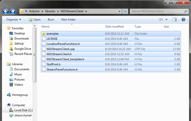
Note: AT&T maintains their own m2x-arduino library, but at the time of this writing, that library did not have a "Delete" function, which is necessary for one of the tutorials. We forked the git repository and added a "Delete" function. If "Delete" is added to the AT&T library, we will update this tutorial to use theirs.
Post Temperature Data
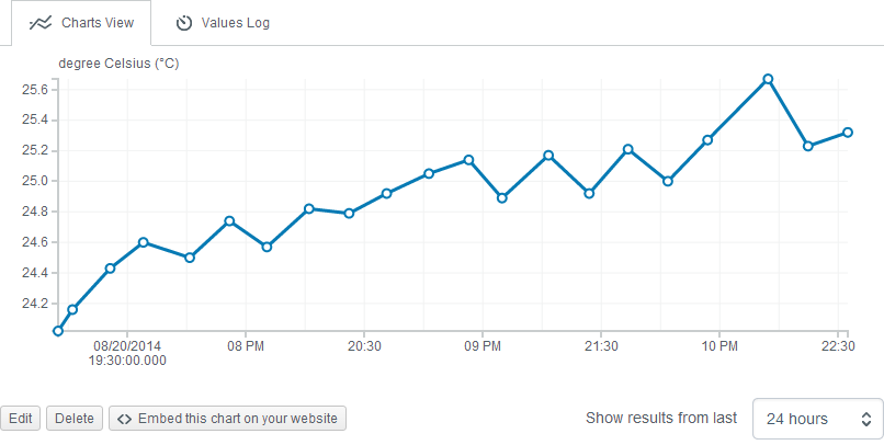
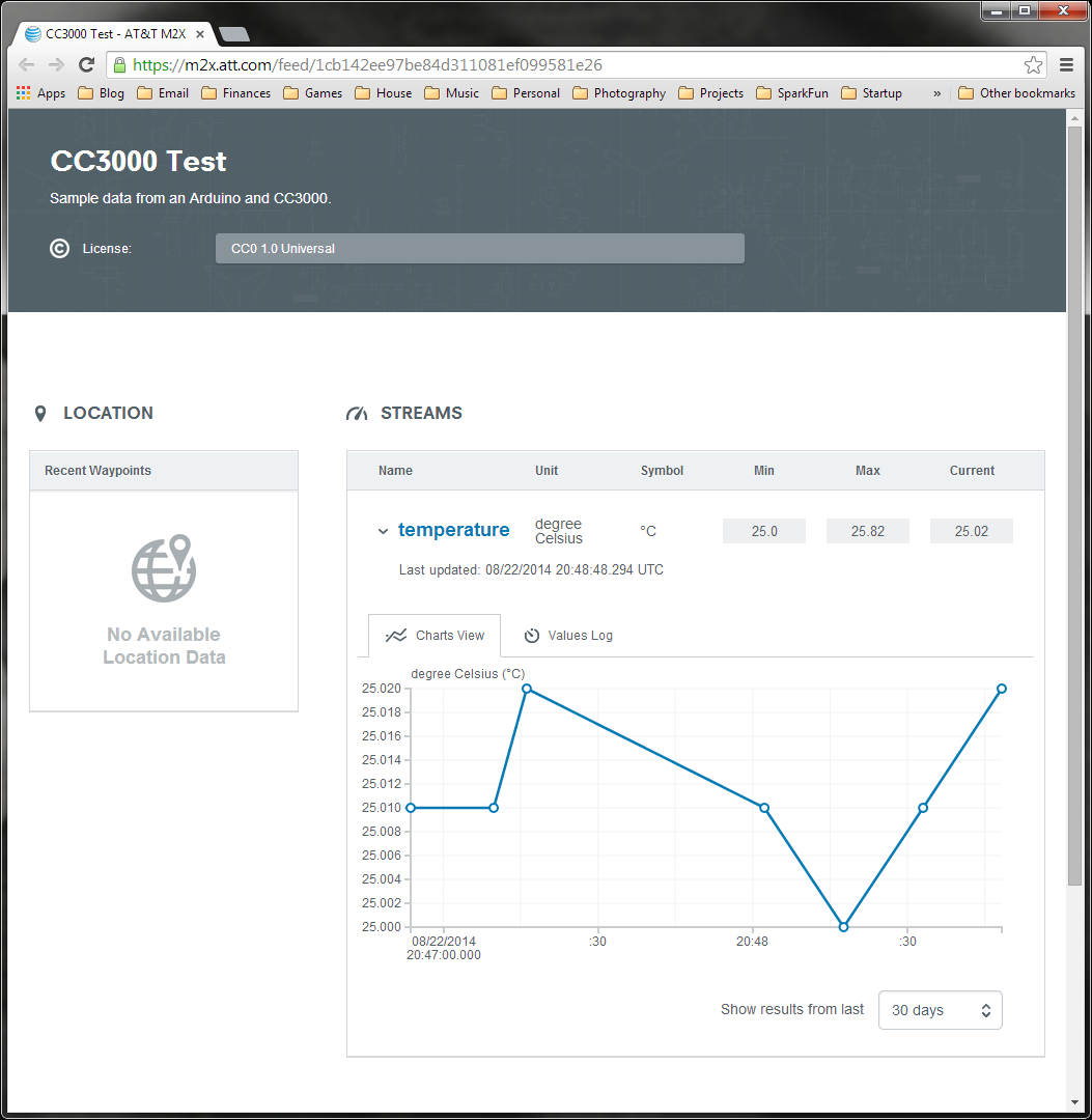
The first logical step in using the M2X service is to create a data stream and post information to it. In this tutorial, we connect a temperature sensor to an Arduino equipped with a CC3000 shield and send temperature readings to our M2X stream. This stream will automatically display the data in an easy-to-read chart for us to look at.
Required Materials
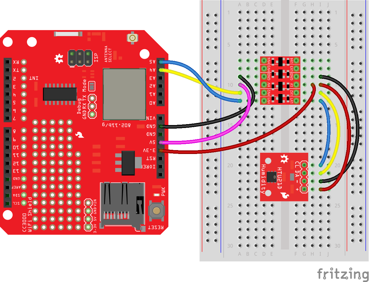
The Circuit
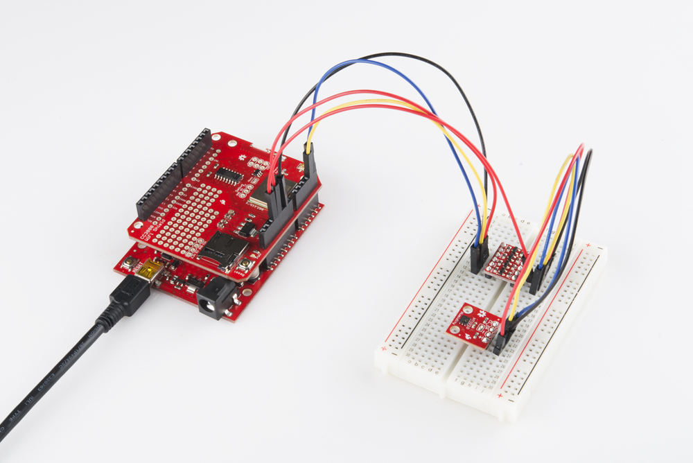
Connect the CC3000 shield to the Arduino, and connect the level shifter and temperature sensor as shown.
Example Code
Open up the Arduino IDE and paste in the following code:
language:c
/****************************************************************
M2X_CC3000_Post.ino
Post temperature data to AT&T's M2X
Shawn Hymel @ SparkFun Electronics
August 19, 2014

Manually connects to a WiFi network and an M2X stream. Reads
temperature data from an HTU21D temperature and posts it to the
M2X stream.

Change AP_SSID, AP_PASSWORD, AP_SECURITY, FEED_ID, STREAM_NAME,
and M2X_KEY to match your WiFi and M2X parameters.

The security mode is defined by one of the following:
WLAN_SEC_UNSEC, WLAN_SEC_WEP, WLAN_SEC_WPA, WLAN_SEC_WPA2

Resources:
Include SPI.h, SFE_CC3000.h, SFE_CC3000_Client.h, jsonlite.h,
M2XStreamClient.h, Wire.h, HTU21D.h

Development environment specifics:
Written in Arduino 1.0.5
Tested with Arduino UNO R3

This code is beerware; if you see me (or any other SparkFun
employee) at the local, and you've found our code helpful, please
buy us a round!

Distributed as-is; no warranty is given.
****************************************************************/

#include <SPI.h>
#include <SFE_CC3000.h>
#include <SFE_CC3000_Client.h>
#include <jsonlite.h>
#include <M2XStreamClient.h>
#include <Wire.h>
#include <HTU21D.h>

// Parameters
#define POST_DELAY_MS   10000 // Post to stream every 10 seconds
#define DEGREE_SYMBOL   176   // Degree symbol for Serial.write

// Pins
#define CC3000_INT      2   // Needs to be an interrupt pin (D2/D3)
#define CC3000_EN       7   // Can be any digital pin
#define CC3000_CS       10  // Preferred is pin 10 on Uno

// Connection info data lengths
#define IP_ADDR_LEN     4   // Length of IP address in bytes

// WiFi Constants
#define AP_SSID         "<SSID>"      // SSID of network
#define AP_PASSWORD     "<PASSWORD>"  // Password of network
#define AP_SECURITY     WLAN_SEC_WPA2 // Security of network
#define TIMEOUT         30000         // Milliseconds

// M2X Constants
#define FEED_ID         "<FFED ID>"
#define STREAM_NAME     "<STREAM NAME>"
#define M2X_KEY         "<M2X MASTER KEY>"

// Global Variables
SFE_CC3000 wifi = SFE_CC3000(CC3000_INT, CC3000_EN, CC3000_CS);
SFE_CC3000_Client client = SFE_CC3000_Client(wifi);
M2XStreamClient m2x_client(&client, M2X_KEY);
HTU21D sensor;
float temp;
int g_response;

// Setup. Configure HTU21D, WiFi, and M2X.
void setup() {

  g_response = 0;

  // Initialize UART for debugging
  Serial.begin(9600);
  Serial.println();
  Serial.println(F("SparkFun CC3000 - M2X Post"));

  // Initialize HTU21D
  sensor.begin();

  // Initialize CC3000 (configure SPI communications)
  if ( wifi.init() ) {
    Serial.println(F("CC3000 initialization complete"));
  } else {
    Serial.println(F("Something went wrong during CC3000 init!"));
  }

  // Connect using DHCP
  Serial.print(F("Connecting to SSID: "));
  Serial.println(AP_SSID);
  if(wifi.connect(AP_SSID, AP_SECURITY, AP_PASSWORD, TIMEOUT)) {
    Serial.println(F("Connected!"));
  } else {
    Serial.println(F("Error: Could not connect to AP"));
  }
}

// Main loop. Post sensor readings at regular intervals.
void loop() {

  // Read sensor
  temp = sensor.readTemperature();

  // Print reading to console with degree symbol and 'C'
  Serial.print(F("Temperature: "));
  Serial.print(temp, 2);
  Serial.write(176);
  Serial.println("C");

  // Post data to your stream
  g_response = m2x_client.post(FEED_ID, STREAM_NAME, temp);

  // If we fail to receive a response, stop running
  Serial.print(F("Post response: "));
  Serial.println(g_response);
  if ( g_response == -1 ) {
    while(1);
  }

  // Wait to post to stream again
  delay(POST_DELAY_MS);
}
Before you can run the code, you will need to update a few variables:
- \<SSID> should be changed to your WiFi network name (SSID)
- \<PASSWORD> is your WiFi password
- Make sure AP_SECURITY matches your WiFi security type (e.g. WPA, WEP)
- Change \
, \ , and \ to match your M2X stream information (see next section)
Make a Data Stream
Log in to https://m2x.att.com/.
Click on the Blueprint that we created ("CC3000 Test").
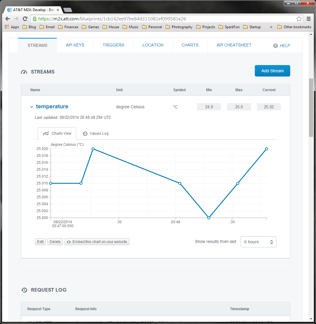
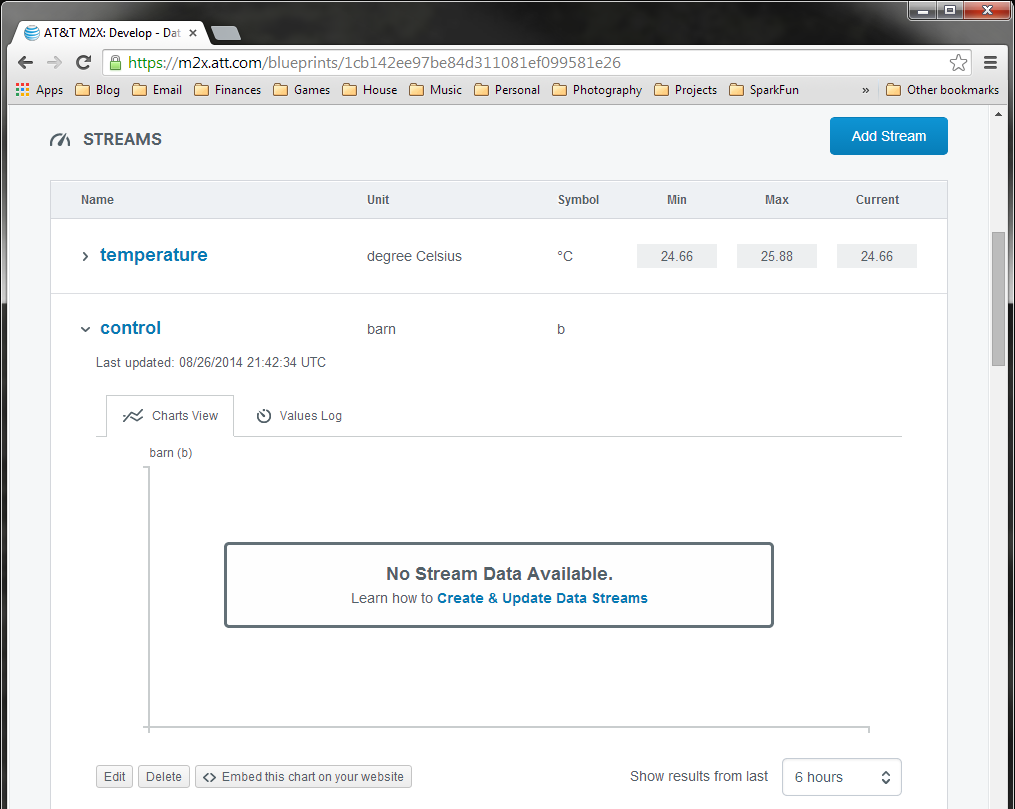
Click on "Add Stream" and fill out some information about your stream. We call it "temperature." Under "Units & Symbol," start typing "Celsius," and you will be presented with a drop-down list. Select "degree Celsius."
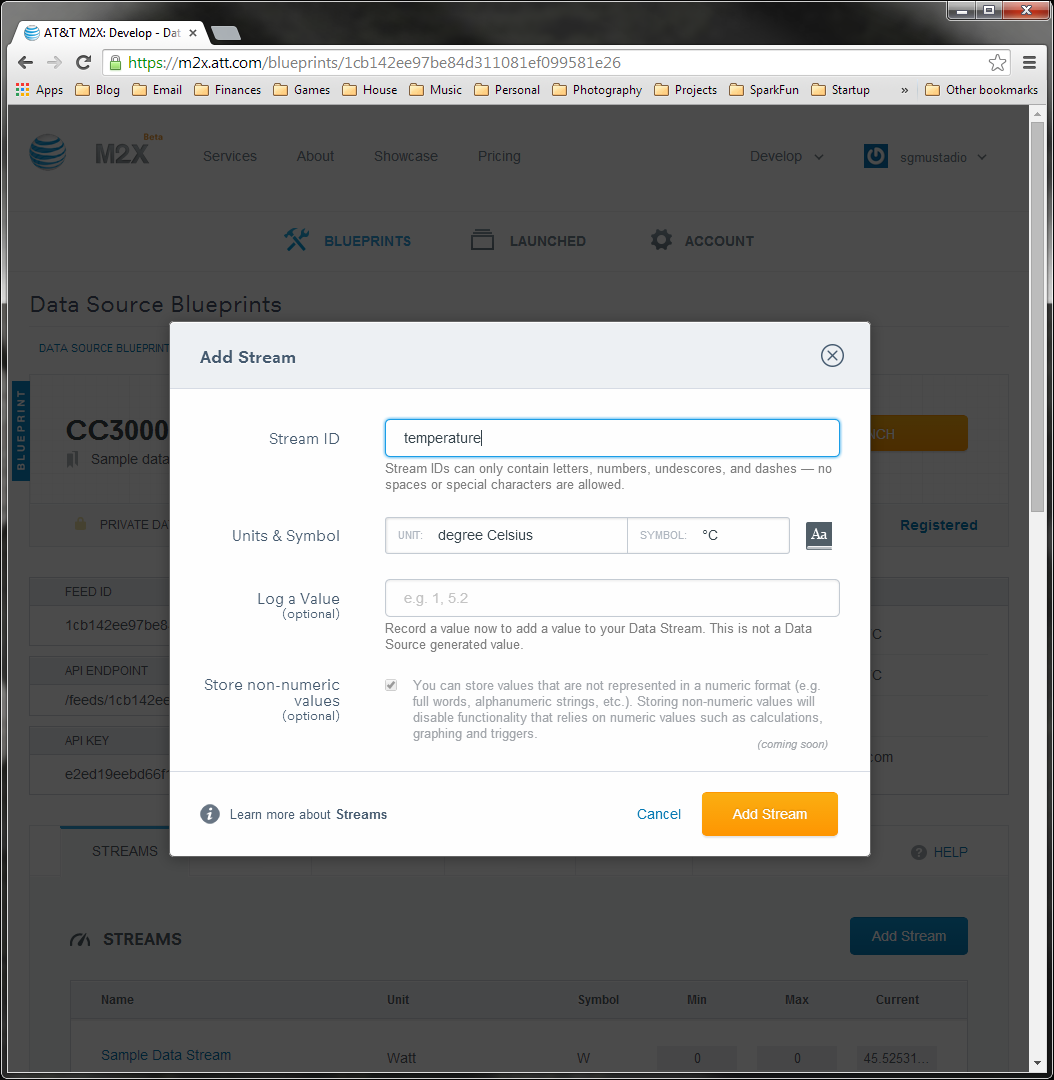
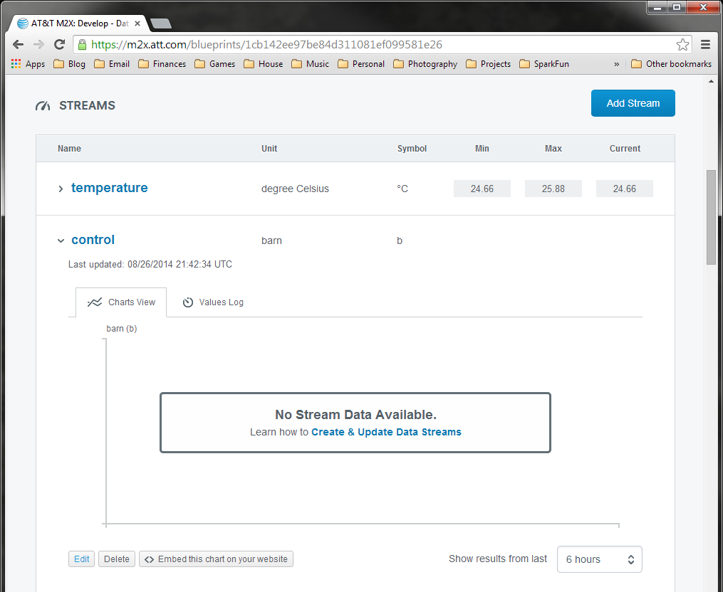
Click "Add Stream." You will be returned to your Blueprint dashboard with a new "temperature" stream added. Click "temperature" to drop down your stream data. There should not be anything in it right now (don't worry, we are about to add some data!).

Scroll up on that same page to find your "FEED ID." Copy that long string and paste it into our M2X_CC3000_Post sketch (replace \
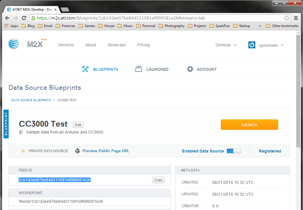
Replace \
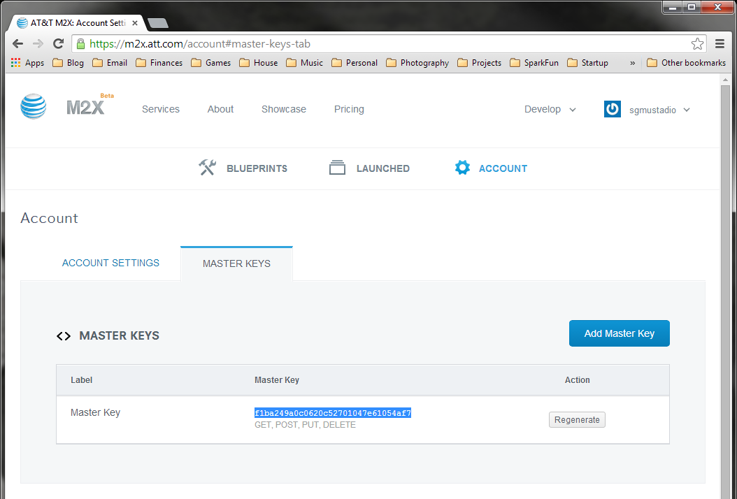
Back on the M2X site, click "ACCOUNT" to go to your account settings.
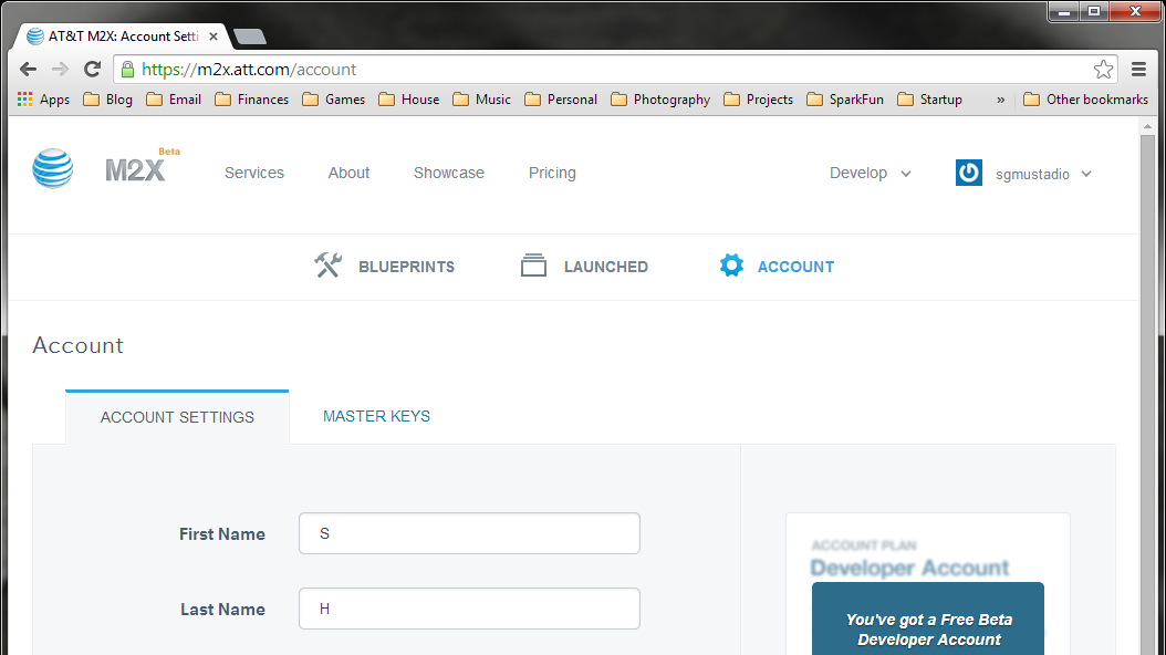
Click on "MASTER KEYS" to see your M2X Master Key. Copy that string and paste it into your code (replace \
Run Your Program
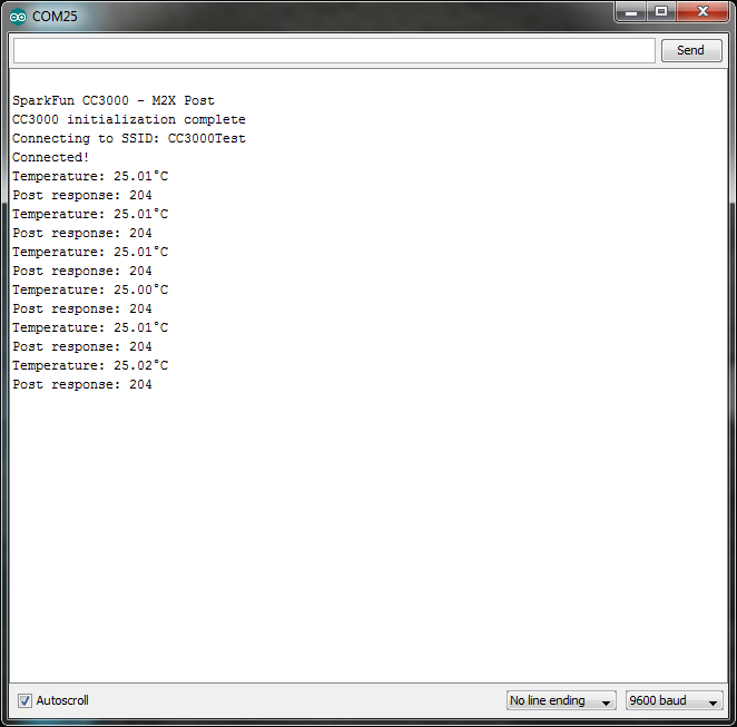
Verify that AP_SSID, AP_PASSWORD, AP_SECURITY, FEED_ID, STREAM_NAME, and M2X_KEY are correct in your code. Click "Upload" and wait for the Arduino IDE to upload the code to your Arduino or RedBoard. Open a Serial Monitor, and you should see temperature data being posted to your M2X stream!
Note: the response should be "204." If you see "404" or "-1" it means there was an error connecting to your WiFi or to the M2X service. If you see "422" it means that your M2X_KEY, FEED_ID, or STREAM_NAME is incorrect. To learn more about response codes, see the M2X API documentation.
Public Data Stream
If you want others to be able to view your data, you can make your Blueprint (and associated streams) public. On the Blueprint dashboard, click the "Edit" button next to your Blueprint name and change the visibility from "Private" to "Public." Click "Save" and wait a few minutes for this to update (this can take upwards of 15 minutes).
Underneath your Blueprint name on the dashboard, click the link "Preview Public Page URL." This will take you to a separate page where you can view the streams associated with that Blueprint. If you made your Blueprint public, you can share this URL with anyone.
Controlling a Device From M2X
Sending information to M2X is great for logging sensor data, but we can also control hardware devices from M2X. This technique requires a bit of trickery, as there is no way to push data to the Arduino (without turning the Arduino into a web server). So, we have the Arduino poll an M2X stream every few seconds looking for data. If it sees a "0" it will turn off the LED. If it sees any other value, it will turn the LED on. Any time the Arduino reads data from the stream, it immediately deletes all data on the stream.
Required Materials
The Circuit
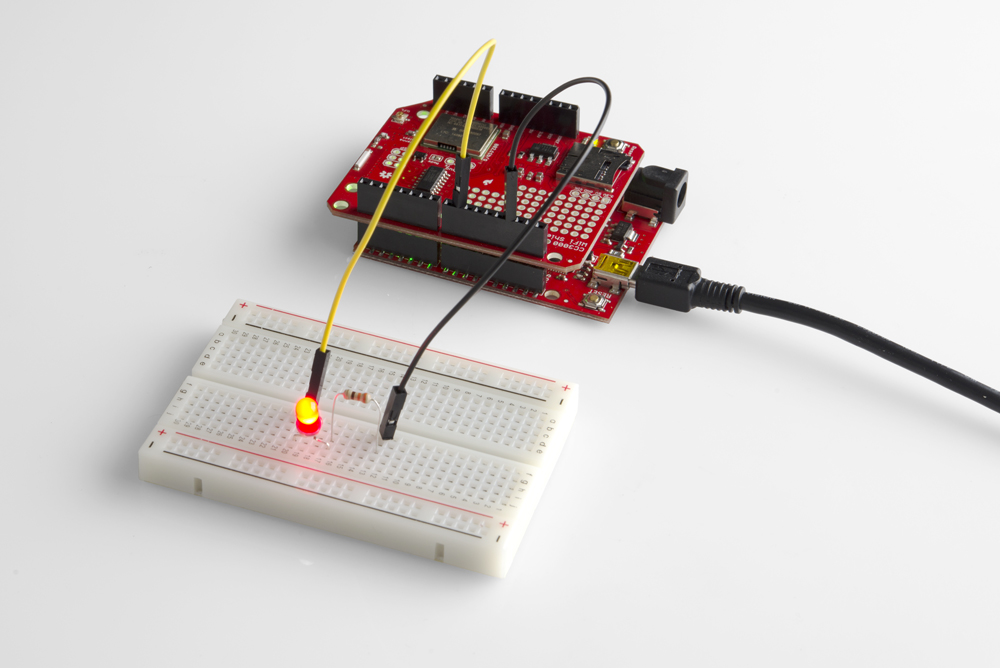
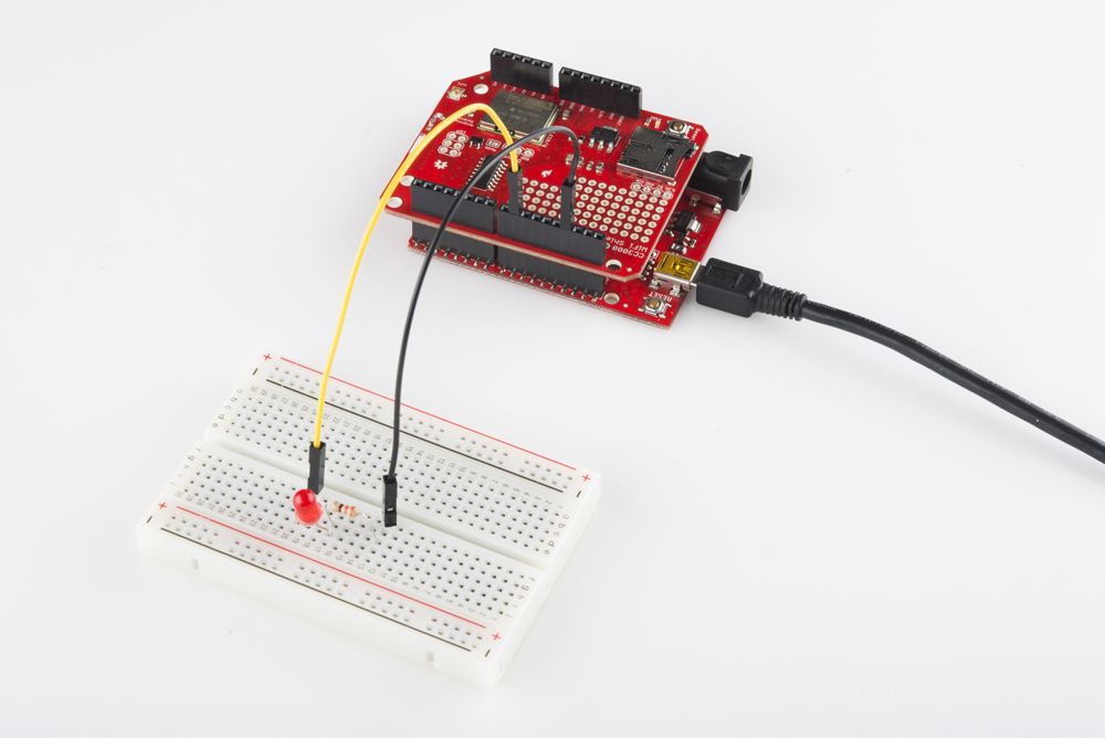
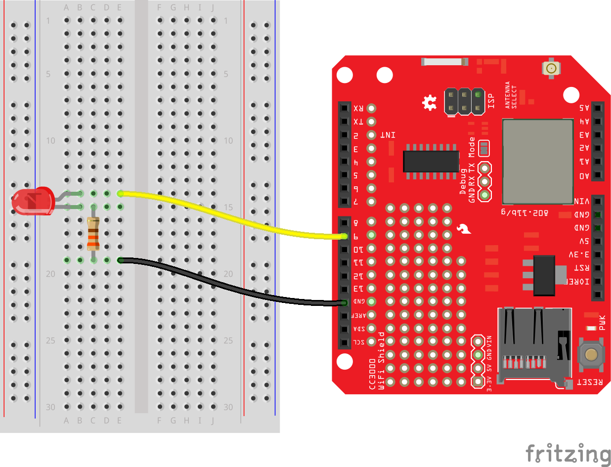
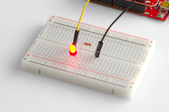
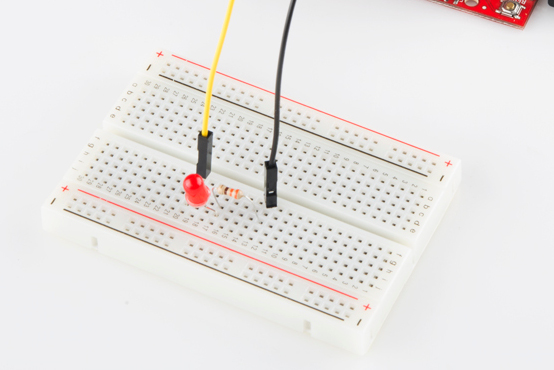
Connect the CC3000 shield to the Arduino, and connect the resistor and LED as shown.
Make M2X Stream
Rather than use our "temperature" stream, we are going to make another stream in the same Blueprint. We will poll this stream from the Arduino, read values, and delete entries as we read them.
Log in to your AT&T M2X account.
Click on your Blueprint (e.g. "CC3000 Test").
Scroll down, and click on "Add Steam." Name the stream something memorable (we'll call ours "control"). Pick any Unit and Symbol (it really does not matter. "Barn" seemed like a silly unit, so we used that).
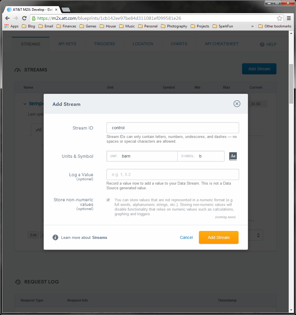
Click "Add Stream." Don't add any values! We will add some data later.
Adjust Serial Buffer
Sadly, the poor Arduino UNO (i.e. ATmega328P) simply does not have enough RAM to control the CC3000 and process the incoming M2X data. To free up some space in the RAM, we are going to reduce the size of the Serial buffer. Don't forget to change it back for your other projects!
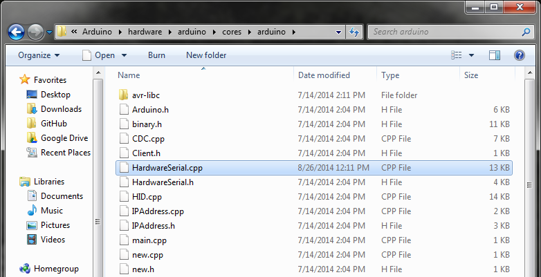
Navigate to \
Note: If you are using a different Arduino with more RAM (e.g. the Arduino Mega), then you don't need to perform this step.
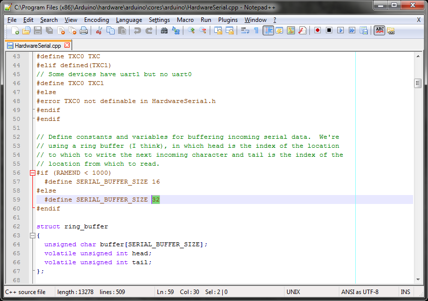
Scroll down and change SERIAL_BUFFER_SIZE from 64 to 32.
Example Code
Open up the Arduino IDE and paste in the following code:
language:c
/****************************************************************
M2X_CC3000_LED.ino
Control an LED with AT&T's M2X
Shawn Hymel @ SparkFun Electronics
August 19, 2014

Manually connects to a WiFi network and performs a GET to the
provided M2X stream. It reads the last data point available
and deletes all data points. This acts as a "producer-consumer"
model.

IMPORTANT: This WILL cause an Uno to run out of RAM. You need to
change SERIAL_BUFFER_SIZE from 64 to 32 in HardwareSerial.cpp,
which can be found in:
C:\Program Files (x86)\Arduino\hardware\arduino\cores\arduino

Change AP_SSID, AP_PASSWORD, AP_SECURITY, FEED_ID, STREAM_NAME,
and M2X_KEY to match your WiFi and M2X parameters.

The security mode is defined by one of the following:
WLAN_SEC_UNSEC, WLAN_SEC_WEP, WLAN_SEC_WPA, WLAN_SEC_WPA2

Resources:
Include SPI.h, SFE_CC3000.h, SFE_CC3000_Client.h, jsonlite.h,
M2XStreamClient.h

Development environment specifics:
Written in Arduino 1.0.5
Tested with Arduino UNO R3

This code is beerware; if you see me (or any other SparkFun
employee) at the local, and you've found our code helpful, please
buy us a round!

Distributed as-is; no warranty is given.
****************************************************************/

#include <jsonlite.h>
#include <SPI.h>
#include <SFE_CC3000.h>
#include <SFE_CC3000_Client.h>
#include <M2XStreamClient.h>

// Parameters
#define POLL_DELAY_MS   1000 // Poll M2X stream every 1 second

// Pins
#define CC3000_INT      2    // Needs to be an interrupt pin (D2/D3)
#define CC3000_EN       7    // Can be any digital pin
#define CC3000_CS       10   // Preferred is pin 10 on Uno
#define LED_PIN         9    // LED (we can't use pin 13!)

// Connection info data lengths
#define IP_ADDR_LEN     4    // Length of IP address in bytes
#define TIME_LEN        25   // Length of timestamp string

// WiFi Constants
#define AP_SSID         "<SSID>"      // SSID of network
#define AP_PASSWORD     "<PASSWORD>"  // Password of network
#define AP_SECURITY     WLAN_SEC_WPA2 // Security of network
#define TIMEOUT         30000         // Milliseconds

// M2X Constants
#define FEED_ID         "<FFED ID>"
#define STREAM_NAME     "<STREAM NAME>"
#define M2X_KEY         "<M2X MASTER KEY>"
#define FROM_TIME       "1970-01-01T00:00:00.000Z"

// Global Variables
SFE_CC3000 wifi = SFE_CC3000(CC3000_INT, CC3000_EN, CC3000_CS);
SFE_CC3000_Client client = SFE_CC3000_Client(wifi);
M2XStreamClient m2x_client(&client, M2X_KEY);
uint8_t g_new;
int g_response;
int g_index;
char g_time[TIME_LEN];
uint8_t led_state;

// M2X fetch callback. This is called for each entry found.
void on_data_point_found( const char* at, \
                          const char* value, \
                          int index, \
                          void* context) {

  // Index 0 is the most recent. Save the timestamp so we can
  // delete all the entries up to that point. If the value is
  // exactly 0, turn off the LED. Otherwise, turn it on.
  if ( index == 0 ) {
    g_new = 1;
    strncpy(g_time, at, TIME_LEN);
    if ( strcmp(value, "0") == 0 ) {
      led_state = 0;
    } else {
      led_state = 1;
    }
  }
}

// Setup. Configure WiFi and M2X connections.
void setup() {

  g_response = 0;
  g_new = 0;

  // Initialize LED
  led_state = 0;
  pinMode(LED_PIN, OUTPUT);
  digitalWrite(LED_PIN, LOW);

  // Initialize UART for debugging
  Serial.begin(9600);
  Serial.println();
  Serial.println(F("SparkFun CC3000 - M2X LED"));

  // Initialize CC3000 (configure SPI communications)
  if ( wifi.init() ) {
    Serial.println(F("CC3000 initialization complete"));
  } else {
    Serial.println(F("Something went wrong during CC3000 init!"));
  }

  // Connect using DHCP
  Serial.print(F("Connecting to SSID: "));
  Serial.println(AP_SSID);
  if(wifi.connect(AP_SSID, AP_SECURITY, AP_PASSWORD, TIMEOUT)) {
    Serial.println(F("Connected!"));
  } else {
    Serial.println(F("Error: Could not connect to AP"));
  }
}

// Main loop. Poll M2X stream, update LED, and delete entries.
void loop() {

  // Fetch values from M2X stream
  g_response = m2x_client.fetchValues(FEED_ID, \
                                      STREAM_NAME, \
                                      on_data_point_found, \
                                      NULL);

  // If we fail to receive a reponse, stop running
  Serial.print(F("Fetch response: "));
  Serial.println(g_response);
  if ( g_response == -1 ) {
    while(1);
  }

  // Update LED and delete entries if there was a new value
  if ( g_new ) {

    // Update LED state
    digitalWrite(LED_PIN, led_state);
    Serial.print(F("LED: "));
    Serial.println(led_state);

    // Fetch drops last 4 chars. Add some so we can delete entries.
    strncpy(g_time + 20, "999Z", 5);

    // Delete all entries
    g_response = m2x_client.deleteValues( FEED_ID, \
                                          STREAM_NAME, \
                                          FROM_TIME, \
                                          g_time);

    // If we fail to receive a reponse, stop running
    Serial.print(F("Delete response: "));
    Serial.println(g_response);
    if ( g_response == -1 ) {
      while(1);
    }

    // Reset new flag
    g_new = 0;
  }

  // Wait to poll stream again
  delay(POLL_DELAY_MS);
}
Don't forget to update the WiFi and M2X stream parameters:
- \<SSID> should be changed to your WiFi network name (SSID)
- \<PASSWORD> is your WiFi password
- Make sure AP_SECURITY matches your WiFi security type (e.g. WPA, WEP)
- Change \
and \ to match your M2X information (see the Post Temperature Data example) - Change \
to your new stream name (e.g. "control")
Run Your Program
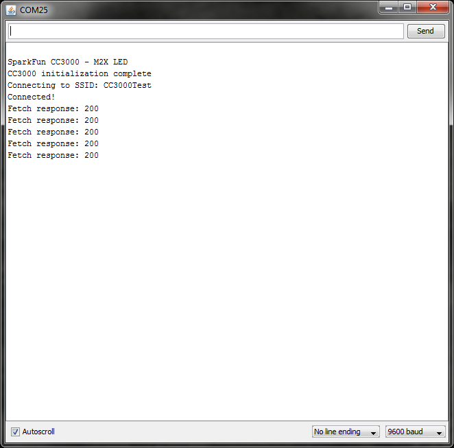
Upload your program to the Arduino. Open up a Serial Monitor, and you should see the Arduino connect to WiFi and start to poll your M2X stream.
While your Arduino is polling the M2X stream, go back to your M2X Blueprint in your browser and expand our new data stream.
Click the "Edit" button and enter a value (anything other than "0") into the "Log a Value" field.
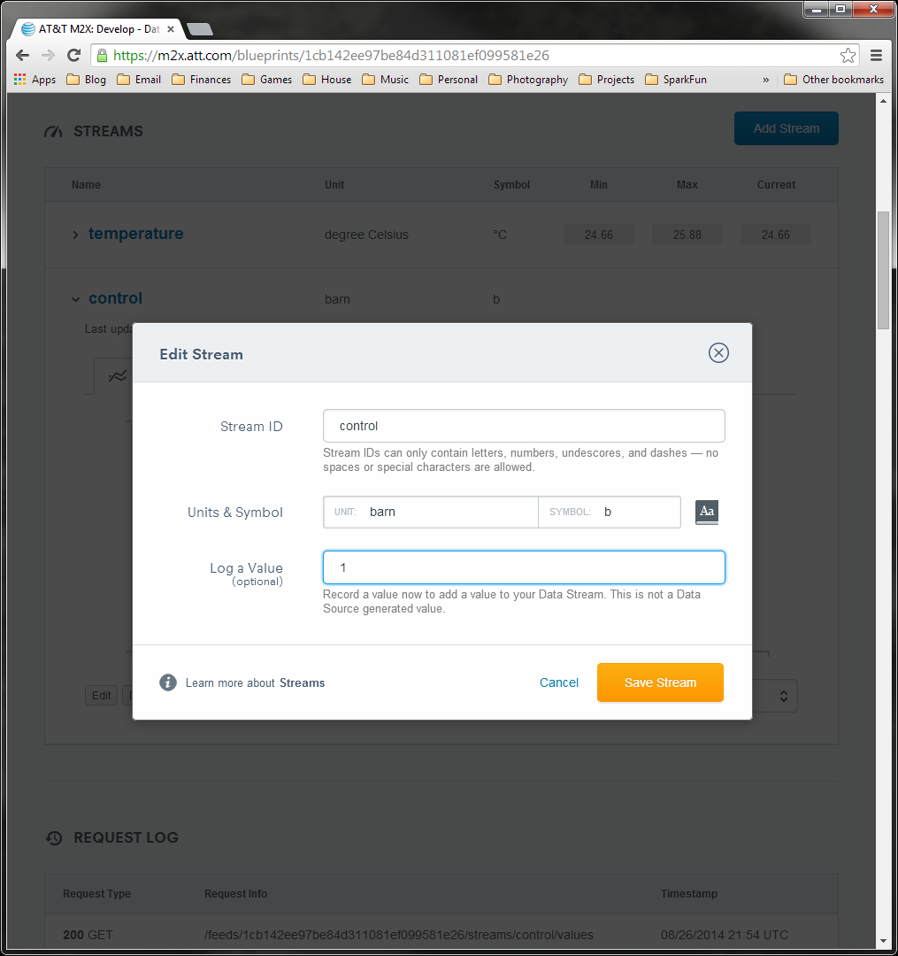
Click "Save Stream." In a few seconds, your Arduino should see that a value was logged to the stream and turn on the LED as a result.
To turn off the LED, click on "Edit" again for your data stream. This time, set "Log a Value" to 0 and click "Save Stream." Your LED should turn off within a few seconds.
So What?
OK, so blinking an LED might seem a little simplistic. However, being able to control a microcontroller from the Internet is a pretty big thing (and will garner the admiration of all your geek friends).
You could write a phone app to control the lights in your house by posting and reading values in M2X. You could remotely start your car, computer, stereo, etc. as long as there is Internet connectivity. The list goes on.
Resources and Going Further
We showed you how to set up an M2X account, connect your Arduino to an M2X stream to post some values, and even how to control an LED from M2X. These examples are really just the first few steps in the Internet of Things world.
Beyond the Tutorial
- Check out the M2X Getting Started Guide
- Read through AT&T's M2X API documentation to learn more about M2X
- Take a look at AT&T's Developer Site to see other ways to communicate with connected devices
- AT&T has some other Arduino examples for M2X that are worth looking at
- M2X also allows you to set up "triggers" on your data stream, which execute some action whenever certain data appears. Read about triggers
- Browse through our sensor category, and find some interesting data to log
- Show off your M2X skills at an upcoming AT&T hackathon