NOTE: This can be a relatively complex and overwhelming product for novice users, due to the numerous configuration options that make it so versatile. Novice users, may want to consider the WAV Trigger or MP3 Trigger first.
The Qwiic Tsunami does need a few additional items, including a pair of(corded)headphones, for users to get started with this tutorial. You may already have a few of these items, including the required USB-C cable, so feel free to modify your cart based on your needs.
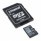
Note: For the best results, we recommend Class 10 SD cards with a FAT16 or FAT32 file system format and a 32kB file allocation size. We recommend avoiding:
The 1GB SparkX SD Card, from our catalog, since it isn't a Class 10 card and can lead to reliability issues.
SD Cards with a capacity larger than 32GB, since it can be difficult to convert them to the FAT16 or FAT32 file system format with a 32kB file allocation size.
For more information on compatible SD cards, please check out the Robertsonics website.
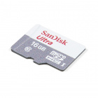
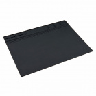
This is a class 10 32GB microSD memory card, perfect for housing operating systems for single board computers and a multitude…
$26.95$14.95
Audio Component Options
Note: For the best results, we recommend connecting the audio output channels from the Qwiic Tsunami to an active amplifier when speakers are used. Otherwise, when speakers are connected directly to the Qwiic Tsunami, without boosting the signal power, users will notice a significant decrease in sound quality of the audio playback.
*Users can connect the audio output channels from any Tsunami board directly to headphones.
Depending on how user want to configure their audio system, some of these audio components might be of interest:
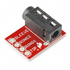
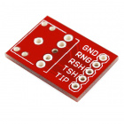
The TRS (tip ring sleeve) jack breakout is a simple board that allows a [1/4" stereo audio jack](https://www.sparkfun.com/pro…
Retired
Trigger Component Options
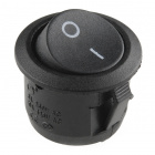
Depending on how users intend to trigger or control the audio playback, users may want to check out the switches and buttons categories from our catalog. Additionally, users can also trigger/control the Qwiic Tsunami through serial and I2C communication.
This assortment of tools is great for those of you who need a solid set of tools to start your workbench on the right foot!
Retired
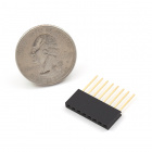
Below is a sample selection of our other headers and soldering tools in our catalog. For a full selection of our available Headers, Hook-Up Wire, or Soldering Tools, click on the associated link.
The RedBoard Artemis takes the incredibly powerful Artemis module from SparkFun and wraps it up in an easy to use and familia…
$24.95
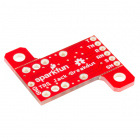
In addition we also offer, Qwiic compatible stackable shields for microcontrollers and pHATs for single board computers (like the Raspberry Pi boards) that don't include a Qwiic connector.
Note: Robertsonics has a more detailed about this product on their Tsunami product page. Robertsonics also provides a cross-platform utility for generating Tsunami configuration files and updating the firmware. All of which, can be downloaded from the Robertsonics' Tsunami downloads page.
If you're unfamiliar with serial terminals, jumper pads, or I2C be sure to checkout some of these foundational tutorials.
How do I install a custom Arduino library? It's easy! This tutorial will go over how to install an Arduino library using the Arduino Library Manager. For libraries not linked with the Arduino IDE, we will also go over manually installing an Arduino library.
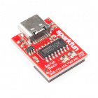
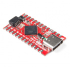
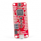
SparkFun Serial Basic Breakout takes advantage of USB-C and is an easy-to-use USB-to-Serial adapter based on the CH340C IC from WCH. With USB-C you can get up to three times the power delivery over the previous USB generation and has the convenient feature of being reversable.
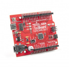
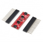
This tutorial covers the basic functionality of the RedBoard Plus. This tutorial also covers how to get started blinking an LED and using the Qwiic system.
The Tsunami Super WAV Trigger also utilizes the Qwiic connect system. We recommend familiarizing yourself with the Logic Levels and I2C tutorials (above) before using it. Click on the banner above to learn more about our Qwiic products.
Hardware Overview
Note: For more details on the Tsunami Super WAV Trigger (Qwiic) check out these resources from the Robertsonics website:
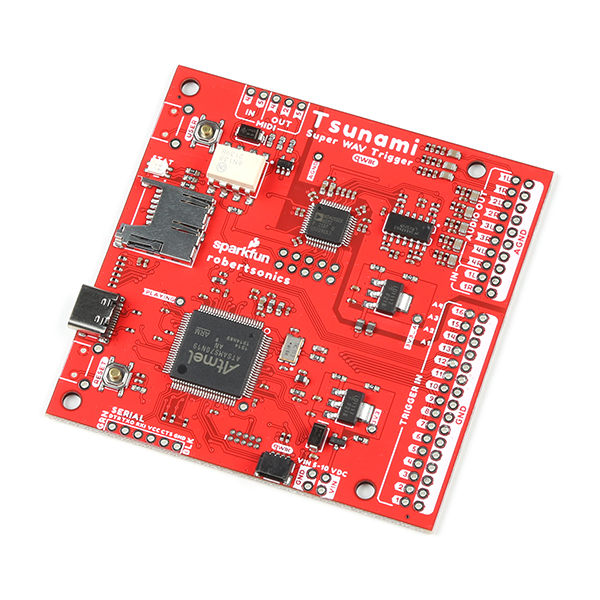
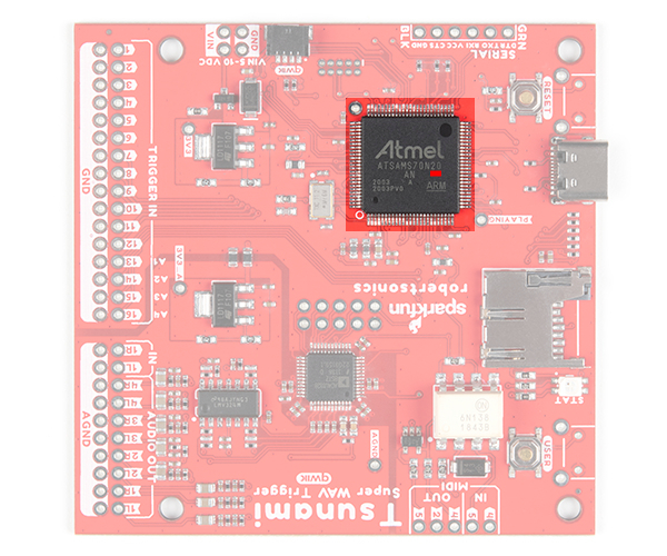
There are currently two versions: Tsunami Super WAV Trigger (Qwiic) and Tsunami Super WAV Trigger - 25 Voice (Qwiic). Both boards use the same PCB labeled as v21. To distinguish between the two, check out the label etched into the microcontroller: ATSAMS70N _ _, where the "_" denotes the different microcontroller that is populated on the board. The Tsunami Super WAV Trigger (Qwiic) uses the ATSAMS70N20 while the Tsunami Super WAV Trigger - 25 Voice (Qwiic) uses the ATSAMS70N19.
ATSAMS70N20 Highlighted on the
Tsunami Super WAV Trigger (Qwiic) - 32 Voices (Qwiic)
ATSAMS70N19 Highlighted on the Tsunami Super WAV Trigger - 25 Voices (Qwiic)
Power
WARNING: The input voltage on the Qwiic Tsunami is limited to 5 - 10V; while the original Tsunami had a voltage range up to 15V. Users swapping or replacing boards should be aware of this change; exceeding the input voltage range will damage the board permanently.
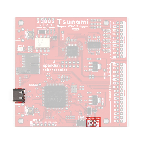
There is a status LED to help make sure that the Qwiic Tsunami is getting power. On the Qwiic Tsunami, users can power the board through either the USB-C connector or the power breakout pins (VIN and GND). We recommend users power the board through the USB-C connector.
The power connections on the Qwiic Tsunami. (Click to enlarge)
The input voltage range for the power pins is 5V - 10V, but we recommend providing a 5V supply. The current draw from the Qwiic Tsunami is approximately 220mA (at 5V) at idle with an SD card inserted. When playing audio files, the current draw increases. (When testing, playing a single .wav file to a mono (single) channel output, the current draw spiked just past 240mA.)
By default, the board's power is isolated from the polarizedQwiic connector system. Although it isn't recommended, users can modify the 3V3_Qwiic jumper to draw power from the Qwiic connector (see jumper section below). The Qwiic system is meant to run on 3.3V, be sure that another voltage is NOT used with the Qwiic system.
Polyphonic Engine
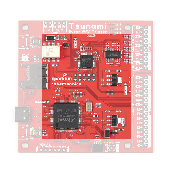
The operation of the polyphonic engine on the Tsunami is proprietary to Robertsonics. While we can't go into exact details on how the board works, here are some highlights of the board:
The primary polyphonic engine components of the Qwiic Tsunami. (Click to enlarge)
Supports up to 4096 uncompressed 16-bit, 44.1kHz mono or stereo WAV files – CD quality
Polyphonic – Play and mix 32 mono or 18 stereo tracks independently and simultaneously
Dynamic routing to 8 mono or 4 stereo outputs
Seamless looping over arbitrary track length
Independent real-time volume and playback rate control per output
Pause and resume individual or groups of tracks
Minimal trigger-to-sound delay: 8 msecs typ, 12 msecs max
Trigger inputs can be individually inverted and set to be edge, latched, or level sensitive
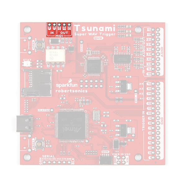
Dedicated MIDI I/O
Assign individual MIDI notes to specific outputs, with individual looping control
Outputs provide independent real-time playback rate control and MIDI Pitch Bend
MIDI Velocity-sensitive triggering of up to 4096 tracks, adjustable attack and release times
Line-level stereo audio input
Output volumes adjustable from +10dB to -70dB
Firmware track fades (attacks & decays)
Extensive serial and I2C control (Default I2C address: 0x13)
Reset button allows changing SD cards without power-cycle
Firmware updates from µSD card. No additional hardware required
Note: For the best results, we recommend Class 10 SD cards with a FAT16 or FAT32 file system format and a 32kB file allocation size. We recommend avoiding:
The 1GB SparkX SD Card, from our catalog, since it isn't a Class 10 card and can lead to reliability issues.
SD Cards with a capacity larger than 32GB, since it can be difficult to convert them to the FAT16 or FAT32 file system format with a 32kB file allocation size.
For more information on compatible SD cards, please check out the Robertsonics website.
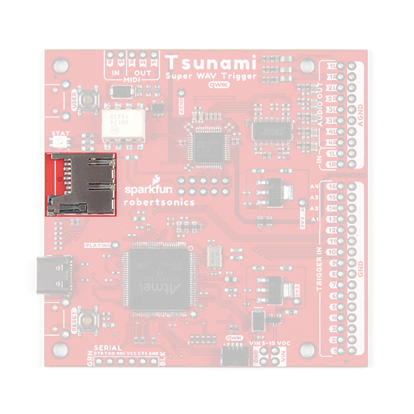
A µSD card is used store the audio *.wav files and initialization tsunami.ini file (optional) for the Qwiic Tsunami. The µSD card slot contains a spring-loaded locking mechanism:
Insert the card and press in to lock the card into the slot.
Press in to unlock and remove the card from the slot.
The µSD card slot on the Qwiic Tsunami. (Click to enlarge)
Buttons
There are two buttons available on the Qwiic Tsunami.
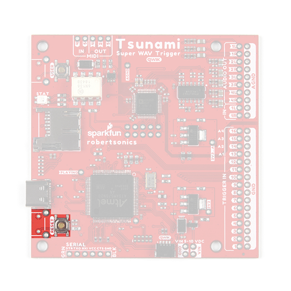
RESET: Used to reset (reinitialize) the board after an SD card has been inserted.
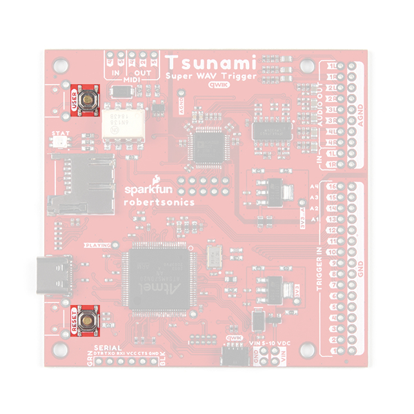
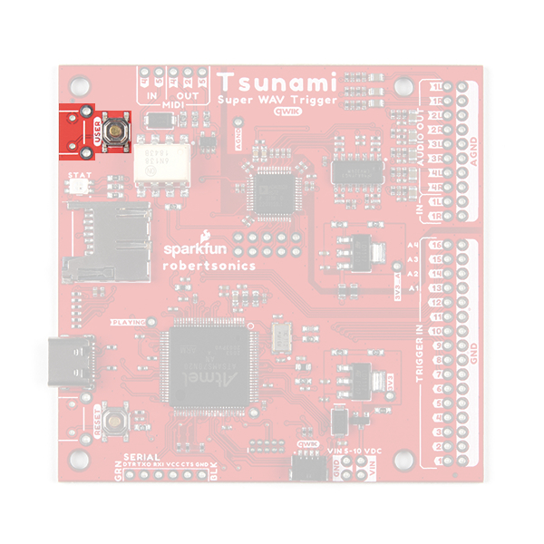
USER: Used to update the firmware from the SD card.
Hold the USER button down
Insert SD card with new firmware tsunamix.hex file (can have normal operation *.wav and *.ini files)
Press RESET button
Wait for successful firmware update status indicator before releasing the USER button
The RESET and USER buttons on the Qwiic Tsunami. (Click to enlarge)
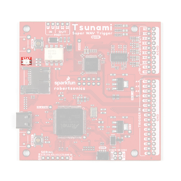
Status LED
New on the Qwiic Tsunami is the RGB status indication LED.
The RGB status LED on the Qwiic Tsunami. (Click to enlarge)
Along with this improvement is a whole list of status indicators for users:
After SD card is inserted and Tsunami is reset:
µSD card found and formatted correctly: 3 short green blinks, then idle state
Error Codes:
No µSD card: One long blue, then idle state
µSD card format error (card installed but can't read FAT): One long red, one short, then idle state
Audio hardware initialization error: One short red, repeats forever (continuous fast blinking red)
During normal operation:
System idle state: 1 very short blue (flash) every 3 seconds.
Audio playing: Solid green.
Error Codes:
Stereo wave file is triggered with the mono firmware, or a mono wave file is triggered with the stereo firmware: 1 long red
No µSD card: One long blue, repeats (slow blinking blue.)
µSD card format error (card installed but can't read FAT): One long red, one short red, repeats
No firmware hex file found, or incorrect file contents: One long red, two short reds, repeats
Flash write error (hardware error): One short red, repeats (fast blinking red.)
Firmware successfully updated: Solid green.
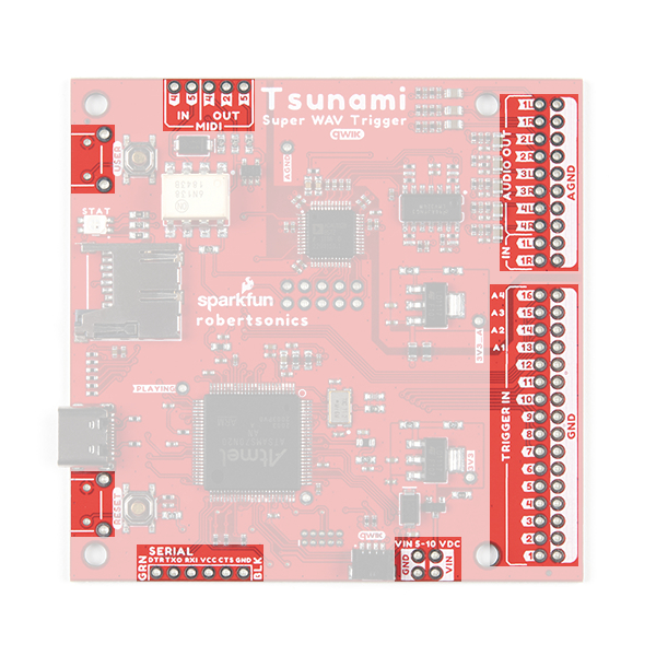
Breakout Pins
Note: All the trigger, serial control, and button pins operate with 3.3V logic. Do not provide 5V to any of these pins; it will permanently damage the board. The exception to this are the MIDI pins, which are opto-isolated.
There are a lot of breakout pins on the Qwiic Tsunami. While we won't cover them all, we'll discuss the pins with major functionality that users would normally interface with.
The breakout pins on the Qwiic Tsunami. (Click to enlarge)
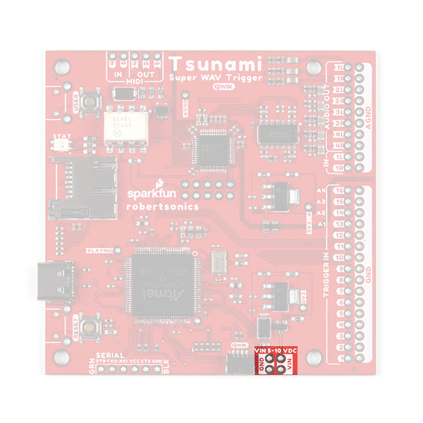
Power Input
While we normally recommend that users power the Qwiic Tsunami through the USB-C connector, there are four power input pins on the bottom of the board for users, who wish to permanently attach an external power source. The input voltage range is 5 - 10V, but we recommend providing a 5V supply.
The power input pins on the Qwiic Tsunami. (Click to enlarge)
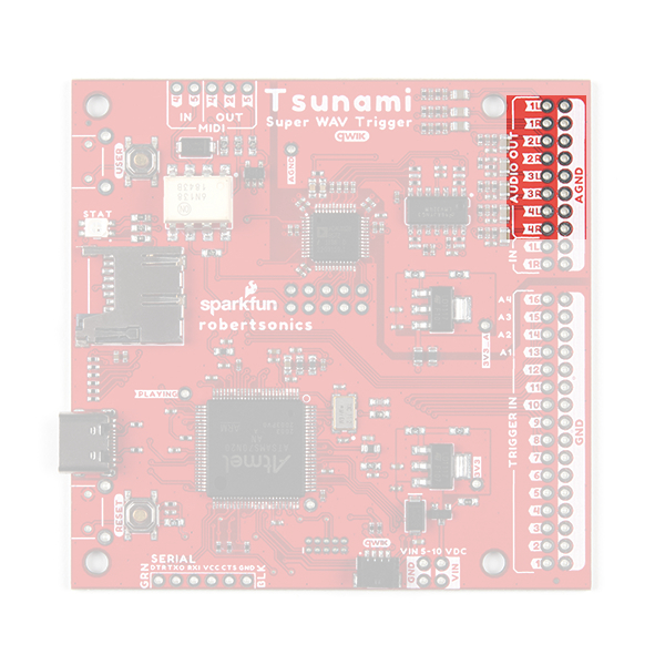
Audio Pins
The audio pins support up to 7.1 channel surround sound (or 8 mono channels) output and stereo (or 2 mono channels) line-level input.
Output Channels
Note:
For impedance matching the audio output channels, the impedance of the speakers or amplifiers should be above 3.8kΩ.
There is significant frequency roll off at the ends of the high and low range of the audio output channels. Extended use in these ranges can potentially damage the audio codec chip.
The audio output channels can be configured as stereo or mono outputs. By default, the factory programmed firmware on the Qwiic Tsunami only supports mono .wav file playback and audio output channels will act independently as eight mono outputs. For the best results, users should be hooking up the audio outputs to an amplifier or active speakers, which include an internal amplifier.
The audio output pins on the Qwiic Tsunami. (Click to enlarge)
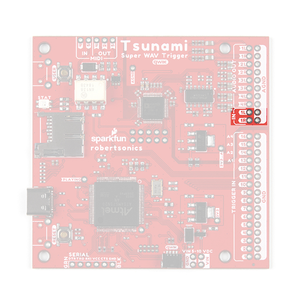
Input Channels
There are two line-level inputs on the Qwiic Tsunami. The inputs have capacitors to negate any DC offsets and are compatible with 1.1VPP signals.
The audio input pins on the Qwiic Tsunami. (Click to enlarge)
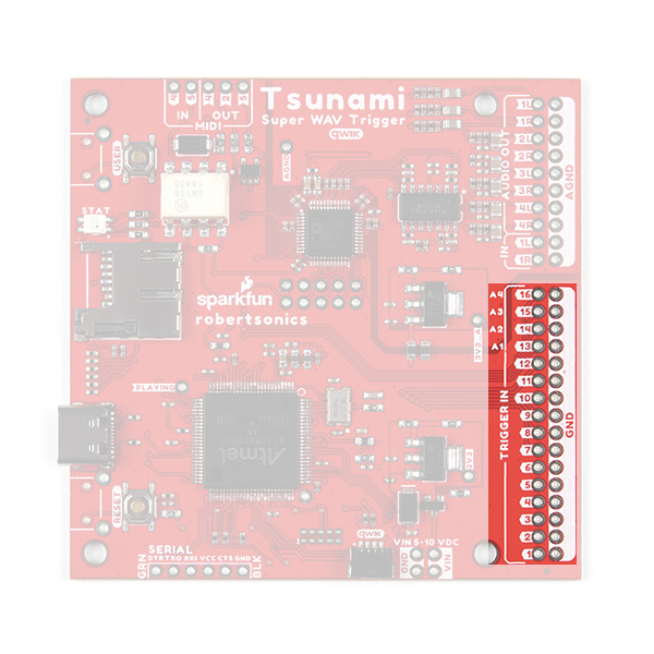
Trigger Pins
Note: Any inputs to the Qwiic Tsunami must use 3.3V logic-levels; otherwise, users risk permanently damaging their board.
The trigger pins are the primary inputs for the Qwiic Tsunami. They can be configured to trigger various actions on the Qwiic Tsunami. By default, the 16 trigger pins are active-high and are triggered by pulling the pins low.
The trigger pins on the Qwiic Tsunami. (Click to enlarge)
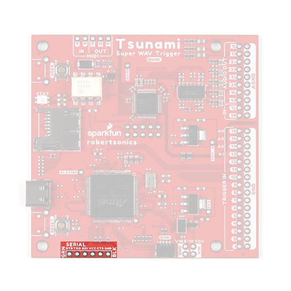
Serial Control
Note: Any inputs to the Qwiic Tsunami must use 3.3V logic-levels; otherwise, users risk permanently damaging their board.
Users have the option of controlling the Qwiic Tsunami through the serial pins. Users can directly connect a USB-to-serial UART bridge like the Serial Basic Breakout or they can connect a microcontroller like the RedBoard Qwiic Plus.
The serial control pins on the Qwiic Tsunami. (Click to enlarge)
MIDI Pins
Note: The MIDI pins are the only exception to the 3.3V logic-level input voltage, as the pins are opto-isolated. Therefore, the pins can directly interface with the 5V logic levels of the MIDI standard.
The MIDI interface pins on the Qwiic Tsunami. (Click to enlarge)
Buttons
There are two PTH breakouts for the two user buttons. These allow users to solder on their own right-angle buttons for a panel mounted operation.
The reset breakout pins on the Qwiic Tsunami. (Click to enlarge)
The user breakout pins on the Qwiic Tsunami. (Click to enlarge)
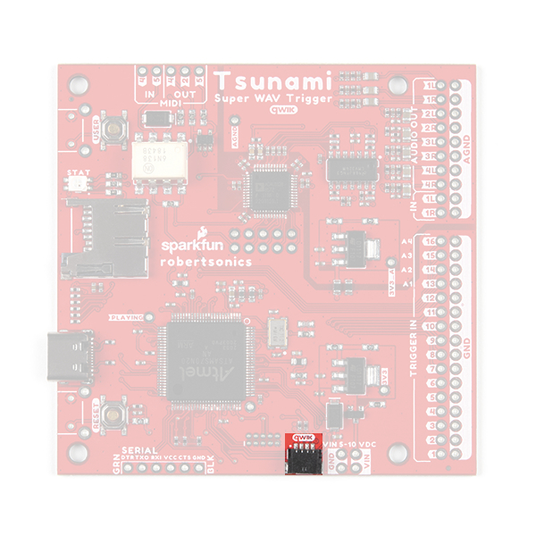
Qwiic Connector
Note: By default, the board's power is isolated from the Qwiic connector system. Although it isn't recommended, users can modify the 3V3 Qwiic jumper to draw power from the Qwiic connector. The Qwiic system is meant to run on 3.3V, be sure that another voltage is NOT used with the Qwiic system.
New for the Qwiic Tsunami, users can now control the board through the an I2C protocol. The polarized Qwiic connector allows users to easily interface with the Qwiic connect system. The Qwiic Tsunami’s default I2C address is 0x13 (7-bit).
The Qwiic connector on the Qwiic Tsunami. (Click to enlarge)
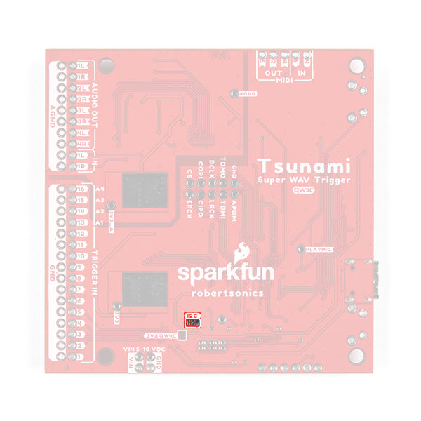
I2C Jumpers
There are two jumpers on the Qwiic Tsunami:
I2C
3V3_Qwiic
Cutting the I2C jumper will remove the 2.2kΩ pull-up resistors from the I2C bus. If you have many devices on your I2C bus you may want to remove these jumpers.
The I2C pull-up resistor jumper on the Qwiic Tsunami. (Click to enlarge)
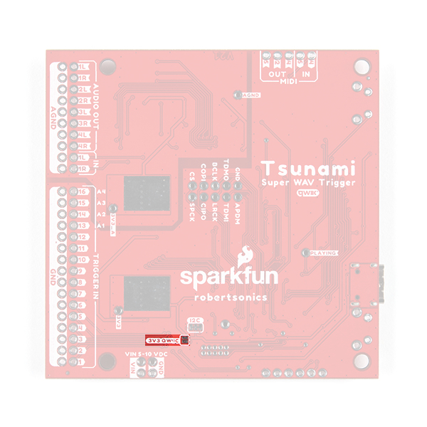
By default, the board's power is isolated from the Qwiic connector system. Bridging the 3V3_Qwiic jumper allows users to connect the board's power to the 3.3V input voltage of the Qwiic connect system.
The 3.3V power jumper on the Qwiic Tsunami. (Click to enlarge)
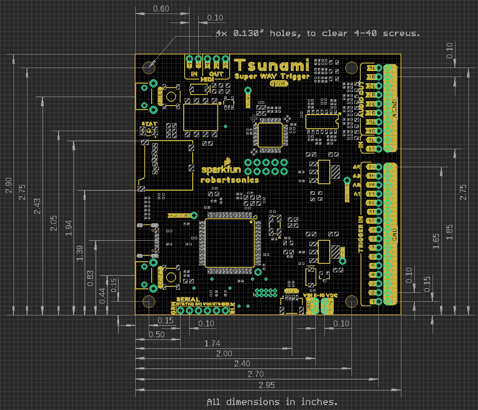
Board Dimensions
The dimensions for the Qwiic Tsunami are essentially the same as the original Tsunami. The overall board size is 2.95" x 2.925" (approx. 7.5cm x 7.4cm) and includes four 0.13" mounting holes, which are compatible with standard 4-40 screws.
The dimensions for the Qwiic Tsunami. (Click to enlarge)
Prepare the μSD Card
Format the µSD Card
Note: For the best results, we recommend Class 10 SD cards with a FAT16 or FAT32 file system format and a 32kB file allocation size. We recommend avoiding:
The 1GB SparkX SD Card, from our catalog, since it isn't a Class 10 card and can lead to reliability issues.
SD Cards with a capacity larger than 32GB, since it can be difficult to convert them to the FAT16 or FAT32 file system format with a 32kB file allocation size.
For more information on compatible SD cards, please check out the Robertsonics website:
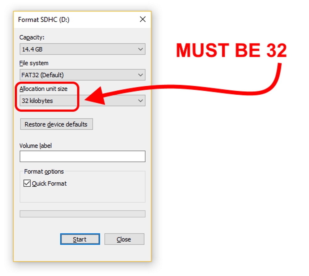
The µSD card is an integral part of the Qwiic Tsunami's operation. In order for the µSD card to be compatible with the Qwiic Tsunami:
A FAT16 or FAT32 file system must be used
The file allocation size must be 32 kilobytes
For a brand new card, formatting may not be necessary. However, if users experience the Qwiic Tsunami missing commands, making occasional strange buzzing sounds, or sometimes crashing, then the file allocation size may be incorrect. The Quick Format option in the Windows operating system is the usually the simplest method to properly format the µSD card.
The format settings for a µSD card with a Windows operating system. (Click to enlarge)
µSD Card Contents
The contents of the µSD card are the key to how the Qwiic Tsunami operates. There are two types of files that the firmware on the Qwiic Tsunami will utilize: audio *.wav files and a tsunami.ini initialization file. The firmware on the Qwiic Tsunami, by default, is configured to operate in the following manner:
Default firmware operation (filenames matching the trigger inputs, will output on the first audio output channel 1L).
If there is a tsunami.ini file on the µSD card on reset, the Qwiic Tsunami will operate on its configuration content.
Any additional changes via I2C or serial commands then take precedence over the initialization file.
Audio Files
The Qwiic Tsunami is designed to playback *.wav audio files from the µSD card. However, the *wav files must be compatible with the firmware on the Qwiic Tsunami.
The audio format of *.wav files must be compatible with the firmware on the Qwiic Tsunami.
By default, the Qwiic Tsunami is factory programmed with the mono audio firmware and will only work with *.wav files in mono audio format.
The filenames if the *wav files must follow the naming convention utilized by the firmware for the Qwiic Tsunami to trigger the audio playback.
Audio File Format
The Qwiic Tsunami plays *.wav files recorded at 16-bit resolution, with a 44.1kHz sampling rate. Different firmware images allow for the playback of stereo or mono files. The Qwiic Tsunami also requires that the files not contain any additional header information. Some audio recording programs, such as Pro Tools, write additional information at the start of the file. An easy way to remove the unnecessary header information is to utilize Audacity. Users can use this software to export a file as WAV (Microsoft) signed 16-bit PCM and clear out the metadata containing the header infromation (i.e. title, artist, genre, etc.).
The following video gives a brief demonstration of the Audacity export process.
Exporting from Audacity to Tsunami. (Click to enlarge)
Note: For users curious about the header contents, Rail John Rogut has written the Header Investigator application, which can display Pro Tools region information and BWF time stamps. This extra data might be meaningful to DAW applications, but Tsunami doesn't use the information.
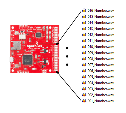
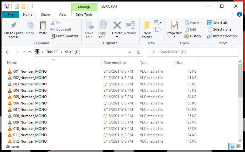
Naming Convention
The filenames contain the trigger input mapping for the Qwiic Tsunami. Each file should start with a three-digit number, which will assign it to a corresponding trigger input.
Example of a filename trigger mapping. (Click to enlarge)
In the example above, the firmware on the Qwiic Tsunami will correspond the filenames of the 16 files numbered 001 to 016 to each of the trigger inputs by default. The triggered *.wav files would be output on the first audio channel (1L).
Initialization File
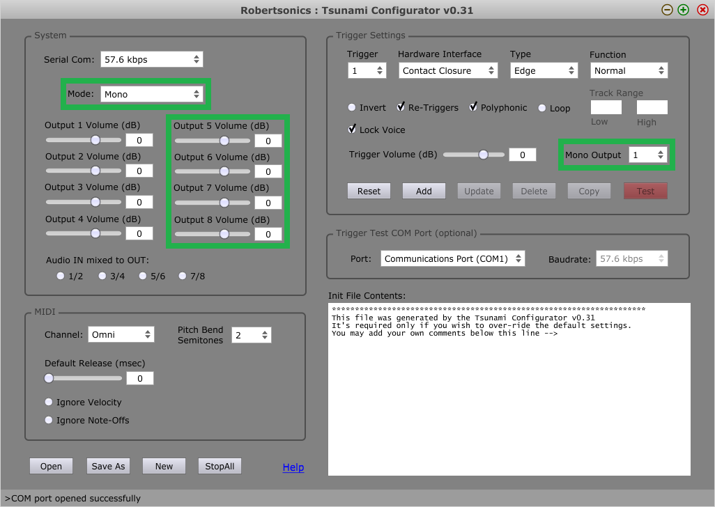
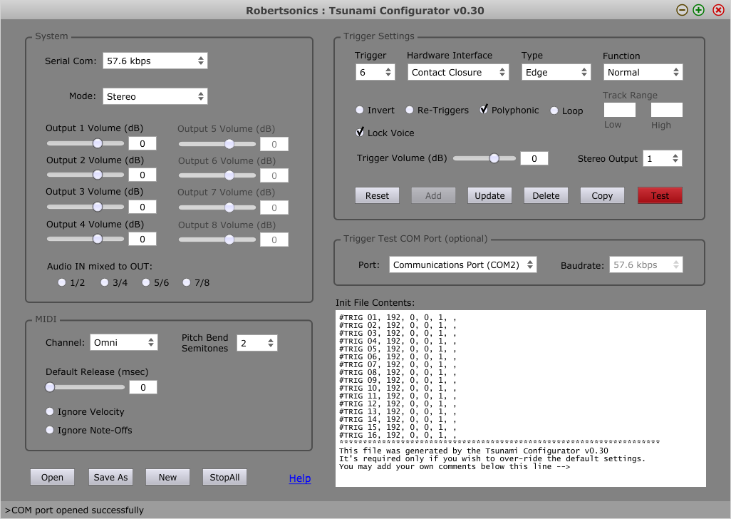
Note: When creating an intialization *.ini file with the configuration tool, users should make sure to select the proper settings for the firmware on the Qwiic Tsunami. By default, the Qwiic Tsunami factory programmed firmware is configured for the mono setting and the configuration tool settings should match the image below:
Example default settings in the configuration tool. (Click to enlarge)
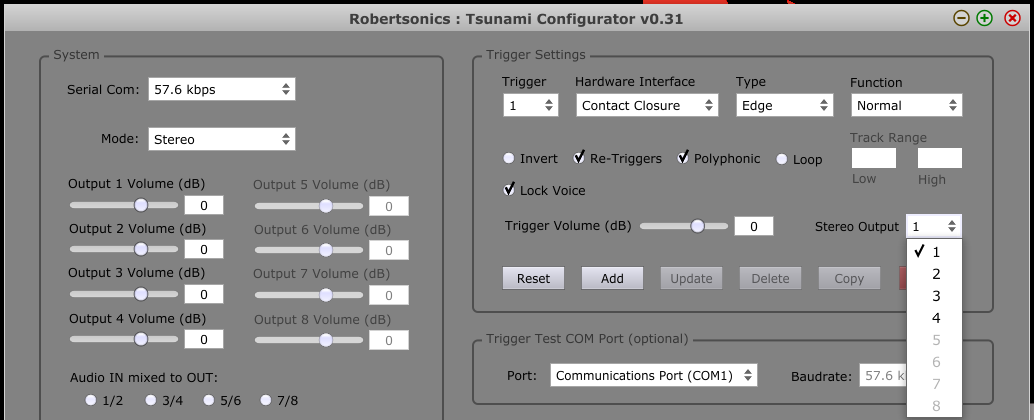
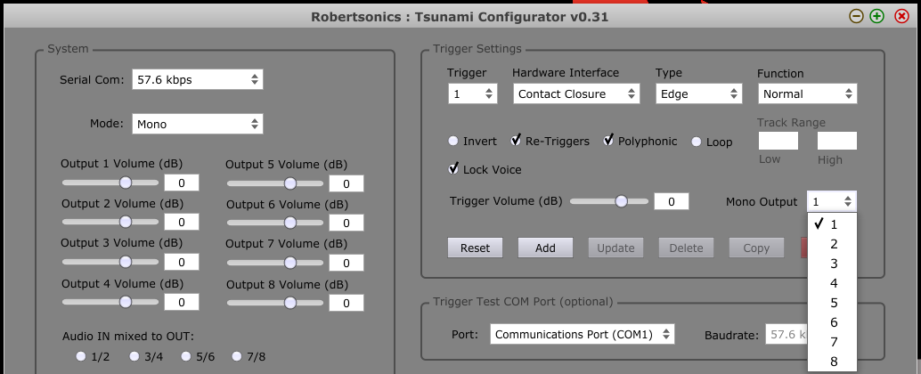
Below is a comparison of the configuration tool appearance between the mono and stereo settings. Users will notice that some of the audio channel output options are greyed-out in the stereo setting.
The stereo setting option for the configuration tool. (Click to enlarge)
The mono setting option for the configuration tool. (Click to enlarge)
There is also an initialization file, tsunami.ini. The Qwiic Tsunami reads this file when it starts, to gather more details about how it should configure the trigger inputs. The *.ini files can be generated and edited using the Tsunami Configurator application. The files contain readable ASCII text, which can be created or edited with a text editor.
The firmware on the Qwiic Tsunami, by default, is configured to operate in the following manner:
Default firmware operation (filenames matching the trigger inputs, will output on the first audio output channel 1L).
If there is a tsunami.ini file on the µSD card on reset, the Qwiic Tsunami will operate on its configuration content.
Any additional changes via I2C or serial commands then take precedence over the initialization file.
Updating the Firmware
When necessary, users can easily update the firmware by saving the file to the µSD card. The latest firmware for the Qwiic Tsunami can be found on Robertsonics website. The file name needs to be changed to tsunami.hex for the bootloader to upload the new firmware. Once the files is saved onto the µSD card, users need to follow the following procedures to update the firmware on the board:
Hold the USER button down
Insert SD card with new firmware tsunamix.hex file (can have normal operation *.wav and *.ini files)
Press RESET button
Wait for successful firmware update status indicator before releasing the USER button
When the status LED is a solid green, the firmware update is complete.
Example Files
For the examples in the following section, users will need to prepare their card with the demonstration files we provide.
Unzip the folder and put the files on the root directory of the card.
Verify the files on the µSD card.
Files on the card
Hardware Assembly
Basic Operation
The basic operation of the Qwiic Tsunami only requires the use of the trigger pins to interact with the board. For the example in the next section, users must insert their configured µSD card with *.wav files and connect their headphones to the Qwiic Tsunami.
Inserting the µSD Card
Inserting the µSD card, prepared from the previous section, is straight forward. The µSD card slot contains a spring-loaded locking mechanism:
Insert the card and press in to lock the card into the slot.
Press in to unlock and remove the card from the slot.
The inserting an µSD card into the Qwiic Tsunami.
Connecting the Headphone Jack
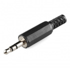
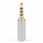
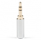
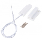
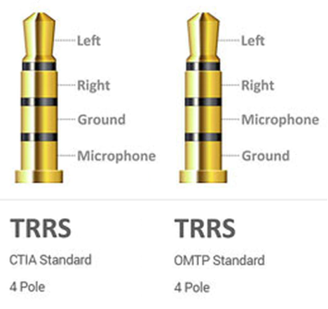
Note: If users experience problems with the audio output to their headphones, there are different headphone connector standards that might be the issue. If that is the case, users only need to swap the connection from SLEEVE pin on TRRS 3.5mm breakout board to the RING2 pin.
Two of the more common variations of the headphone jack connection standards. (Click to enlarge)
Source: quora.com
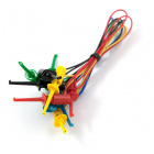
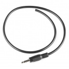
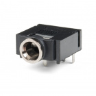
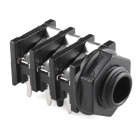
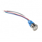
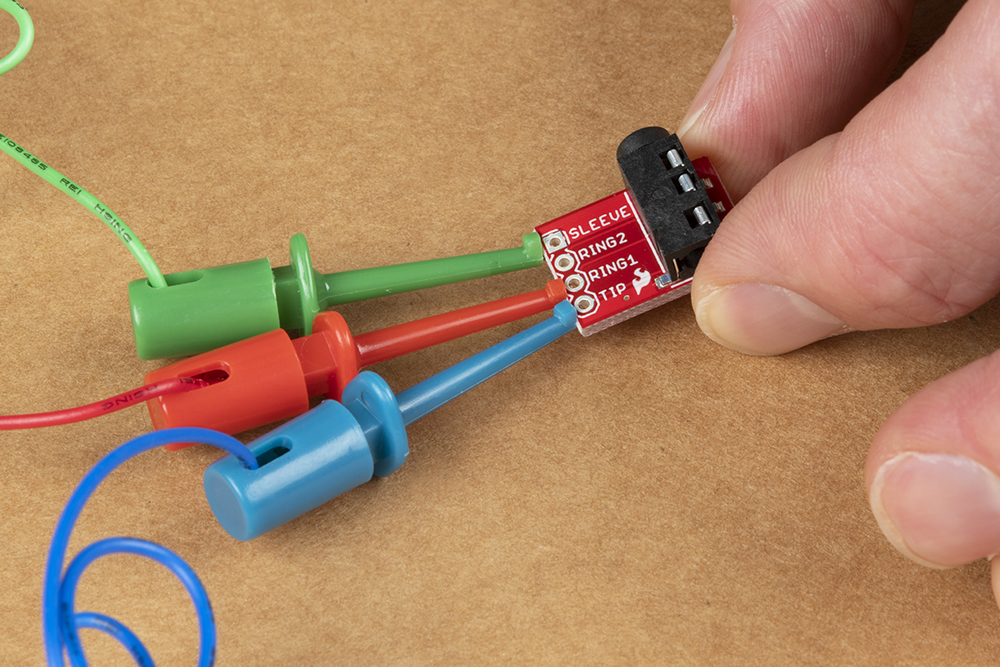
This part of the guide will demonstrate how to temporarily connect a pair of headphones to the audio output channels of the Qwiic Tsunami with the IC hook cables. Connect the TRRS 3.5mm jack breakout board to the Qwiic Tsunami, as illustrated below:
Connect three of the IC hook cables to the TIP, RING1, and SLEEVE pins on the TRRS headphone jack breakout board.
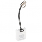
Attaching the IC hooks to the TRRS headphone jack breakout board. (Click to enlarge)
A close up of the IC hooks connected to the pins of the breakout board. (Click to enlarge)
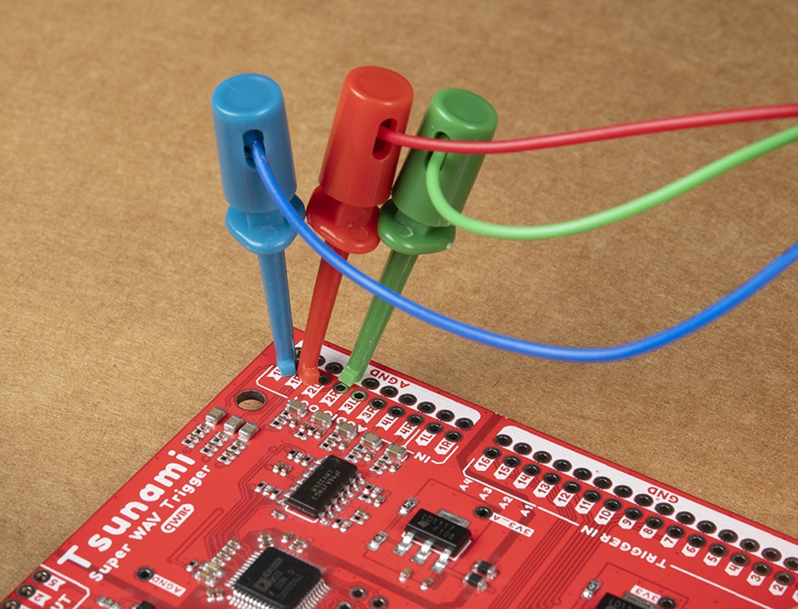
Connect the other end of the cables to the 1L, 1R, and GND audio output pins of the Qwiic Tsunami.
Attaching the IC hooks to the audio output channels of the Qwiic Tsunami. (Click to enlarge)
Below, is a table summarizing the cable connections between the Qwiic Tsunami's pins and the TRRS 3.5mm jack breakout board's pins:
Qwiic Tsunami
TRRS Breakout Board
Cable 1
1L
TIP
Cable 2
1R
RING1
Cable 3
AGND
SLEEVE
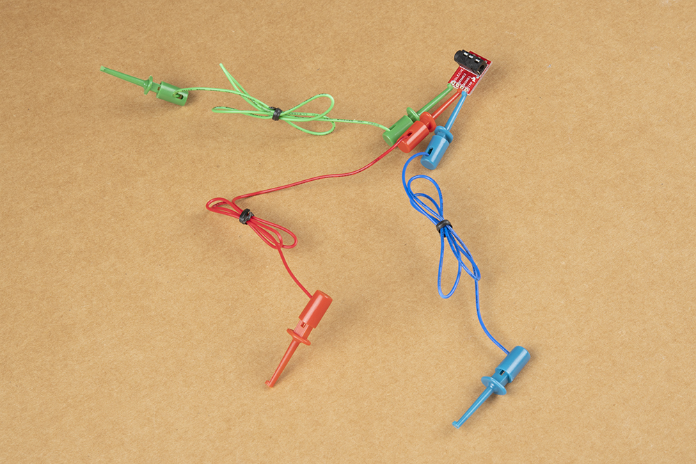
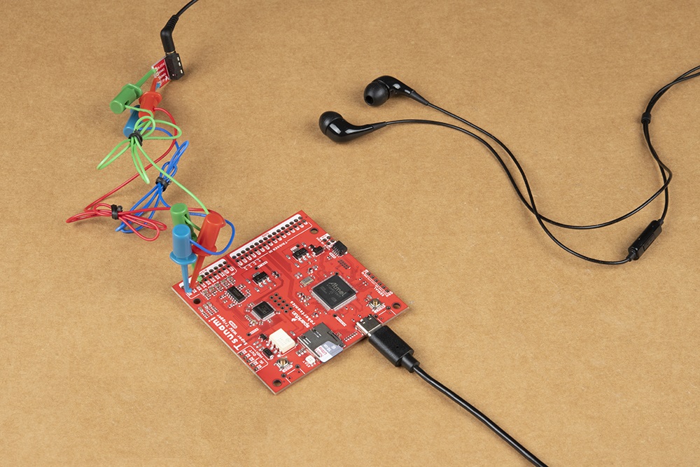
Finally, users will need to connect their headphones to the TRRS 3.5mm jack breakout board. The overall hardware assembly should resemble the image below:
Completed assembly with headphones attached and the Qwiic Tsunami powered through a USB cable. (Click to enlarge)
For a more permanent solution, users can solder the boards together with hook-up wire.
Assembly for Arduino (Qwiic) Example
The assembly for the example in the Arduino library section is similar to the previous assembly. Users only need to connect their RedBoard Plus to the Qwiic Tsunami with a Qwiic cable. The RedBoard Plus should also be connected to their computer with a USB cable.
The assembly for the Arduino library example, with the Redboard Plus connected to the Qwiic Tsunami. (Click to eleagre)
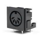
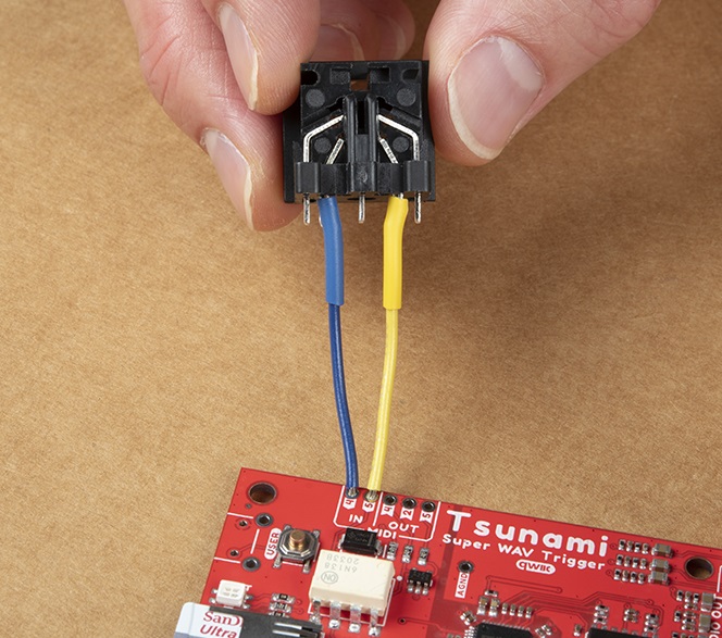
Attaching a MIDI connector to the Qwiic Tsunami. (Click to enlarge)
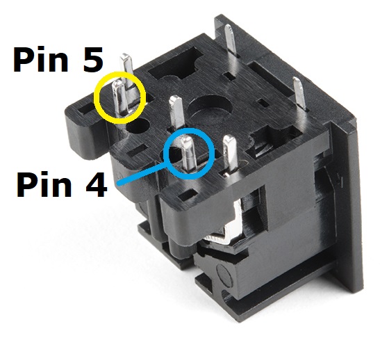
A close up of the MIDI connector pins. (Click to enlarge)
Basic Operation Example
Note: The default firmware is for mono channel operation; therefore, users should only expect audio ouput on one side of their headphone. Users can use the configuration tool to create an initialization file to modify the default operation.
If users experience problems with the audio output to their headphones, there are different headphone connector standards that might be the issue. If that is the case, users only need to swap the connection from SLEEVE pin on TRRS 3.5mm breakout board to the RING2 pin.
Two of the more common variations of the headphone jack connection standards. (Click to enlarge)
Source: quora.com
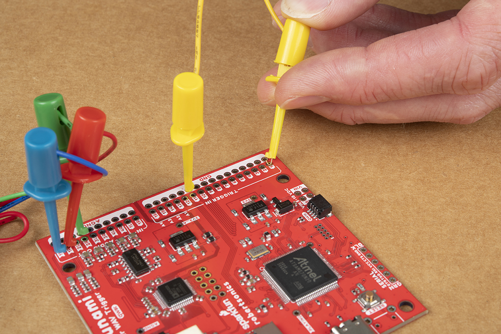
The simplest way to utilize the Qwiic Tsunami is with the trigger pins. The trigger pins are active-high by default; therefore, the pins need to be shorted to ground for the board to react. As a simple demonstration, use one of the IC hook cables to bridge a trigger input to the corresponding ground pads:
Triggering the Qwiic Tsunami to play a *.wav file. (Click to enlarge)
Once the wire makes contact, users should hear a sound on the output on one side of the headphone. The provided demonstration *.wav files are recordings of someone reciting the number of the trigger input. Users should also see the status LED illuminate green while a file is playing.
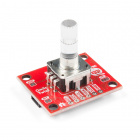
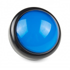
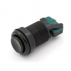
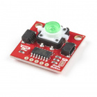
In a more permanent installation users could connect momentary switches, like this large push button.
Arduino Libraries and Example
Note: This example assumes you are using the latest version of the Arduino IDE on your desktop. If this is your first time using Arduino, please review our tutorial on installing the Arduino IDE. If you have not previously installed an Arduino library, please check out our installation guide.
Arduino Libraries
The Qwiic Tsunami is a unique product, in that two different Arduino libraries are available to control the board. For more information on how to install an Arduino library in the Arduino IDE, check out our tutorial below.
How do I install a custom Arduino library? It's easy! This tutorial will go over how to install an Arduino library using the Arduino Library Manager. For libraries not linked with the Arduino IDE, we will also go over manually installing an Arduino library.
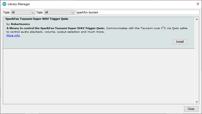
The SparkFun Tsunami Qwiic Arduino Library in the Arduino library manager. Click to enlarge)
Users can install this library through the Arduino Library Manager. Search for SparkFun Tsunami Qwiic Arduino Library and you should be able to install the latest version. Users who prefer manually downloading the libraries from the GitHub repository, can download it here:
The utilization of this library mimics the serial control version to allow users to easily transition between the two. For more details on how to use this library, users can check out the documentation from the serial control library and the Tsunami user guide under "Serial Control".
Tsunami Qwiic Arduino Library Example
Note: If users experience problems with the audio output to their headphones, there are different headphone connector standards that might be the issue. If that is the case, users only need to swap the connection from SLEEVE pin on TRRS 3.5mm breakout board to the RING2 pin.
Two of the more common variations of the headphone jack connection standards. (Click to enlarge)
Source: quora.com
Once you've got the Qwiic version of the library installed, open the Example 01 PlayFile sketch. You can find it under
For users looking for technical assistance, click on the link. There you will find, basic troubleshooting tips and instructions to get started with posting a topic in our forum. Our technical support team will do their best to assist you.
Resources and Going Further
For more information on the Tsunami Super WAV Trigger (Qwiic), check out the links below:
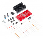
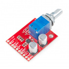
The TSH82 Configurable OpAmp board offers the designer a great balance of performance and flexibility. We'll show you how to get the very best out of your board!
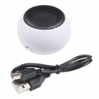
Looking to bring sound into your next embedded project? In this tutorial, we'll walk you through using the SparkFun Audio Player Breakout in combination with the Qwiic Twist to let you select and play tracks from a microSD card.