TMP006 Hookup Guide
This Tutorial is Retired!
This tutorial covers concepts or technologies that are no longer current. It's still here for you to read and enjoy, but may not be as useful as our newest tutorials.
 JordanDee
Hardware Hookup
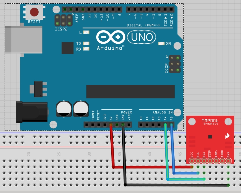
This temperature sensor is easy to hookup and only requires a minimum of four connections. Two for power, VCC and GND, and two for I2C communication, SCL and SDA.
We're going to use the Arduino Uno as an example of how to hook up and talk to this sensor, however, feel free to choose any Arduino or a favorite microcontroller of your choice.
Connections:
- VCC → 5V (or 3.3V)
- GND → GND
- SCL → A5 (or SCL for R3)
- SDA → A4 (or SDA for R3)
Here's a Fritzing diagram showing the physical connections:
Multiple Sensors
If you want to communicate with more than one sensor using the same microcontroller's I2C lines, you will have to give them different addresses by using the address pins, ADR0 and ADR1. By default, both pins are grounded, and the sensor's address is 0x40. Here is a table showing what the address pins should be connected to to establish a different address.
| ADR1 | ADR0 | I2C Address |
|---|---|---|
| GND | GND | 0x40 |
| GND | VCC | 0x41 |
| GND | SDA | 0x42 |
| GND | SCL | 0x43 |
| VCC | GND | 0x44 |
| VCC | VCC | 0x45 |
| VCC | SDA | 0x46 |
| VCC | SCL | 0x47 |
As an example, if you wanted to use two sensors, you could leave one of them as the default address 0x40 and connect the second sensor's ADR0 pin to VCC to change its I2C address to 0x41. This will allow you to talk to both sensors using just one microcontroller.
Data Ready?
The DRDY pin is unnecessary for most applications, however, if you really need to know exactly when a sensor measurement is complete and ready for reading, you can monitor this pin to see when it goes LOW. You can then immediately acquire the temperature measurement data afterward.