Tech Prank: Hardware Mouse Jiggler
 Shawn Hymel
Hardware Assembly
To assemble the entire project, you will first want to de-solder the USB connector from the Pro Micro. Do this by applying flux to all the pads and using a hot air rework station to reflow all the joints while carefully lifting up on the connector with a set of tweezers.

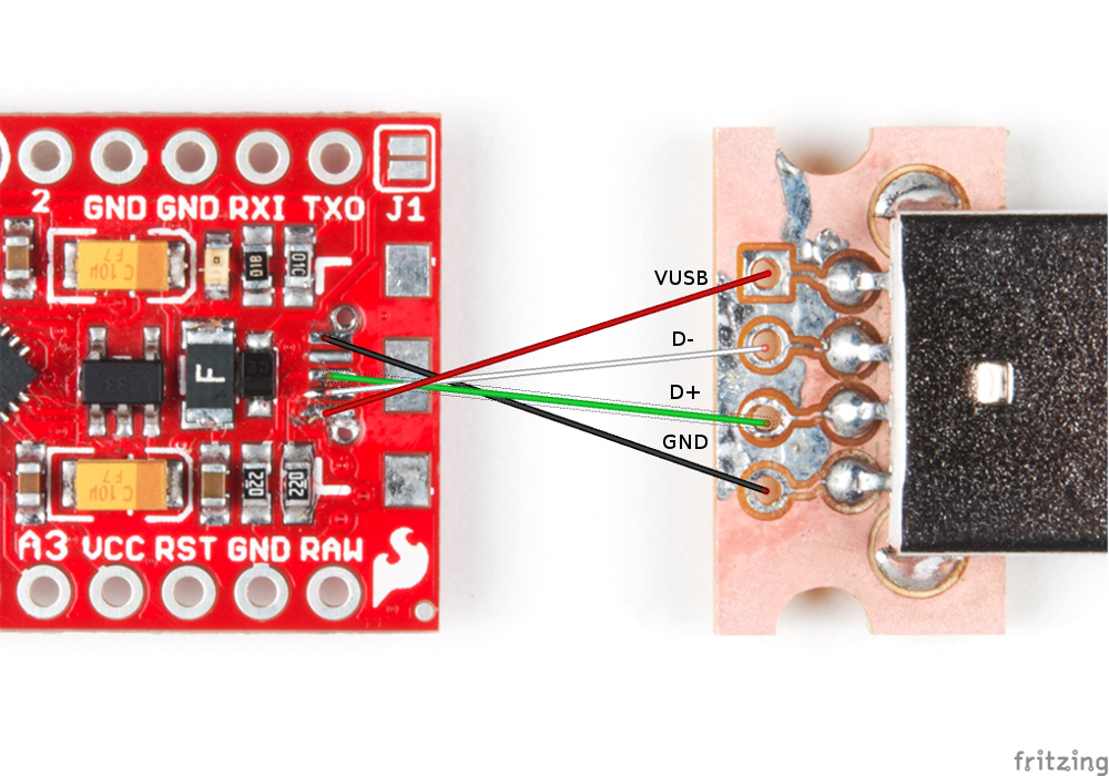
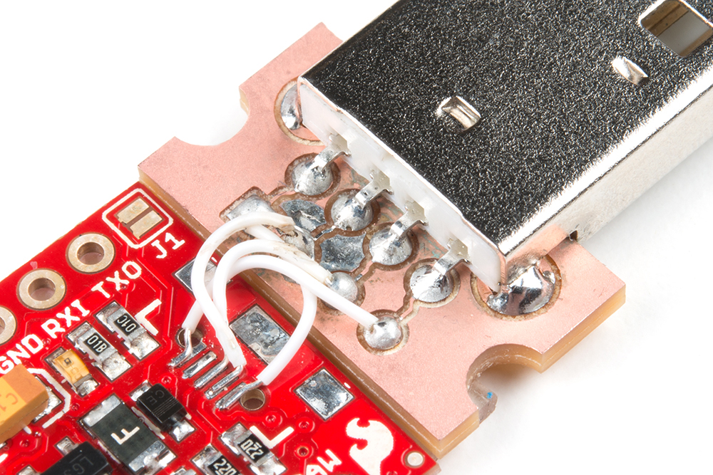
Place the USB connector breakout next to the Pro Micro, and carefully solder 30 AWG wires from the bare USB micro pads on the Pro Micro to the through holes on the breakout board. Note that you'll need to have the wires cross over each other to make sure the right connections are made (otherwise you might fry your Pro Micro, like I did on my first attempt). The connections that you need to make are found in the diagram below.
Carefully bend the wires so that the USB breakout board and Pro Micro are flush next to each other.
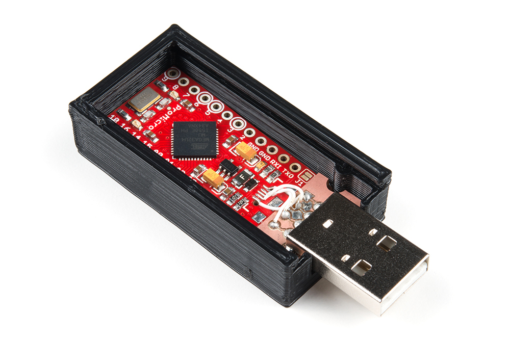
Apply some foam tape or servo tape to the bottom of the Pro Micro and USB board.

Place them inside the 3D printed case, pressing down to adhere them to the enclosure.
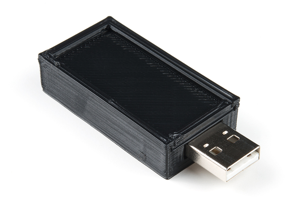
Slide the enclosure's top into the grooves to cover the boards.
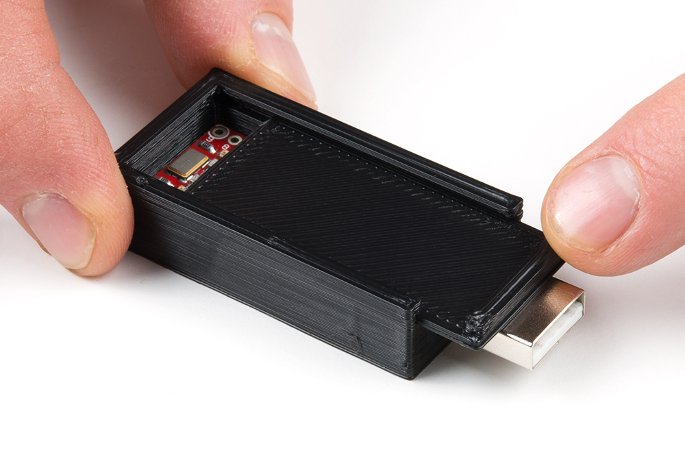
The hardware assembly is done! You should be able to plug it into your computer like this to program it from the Arduino software.