STM32 Thing Plus Hookup Guide
 Alex the Giant, Ell C
 Introduction
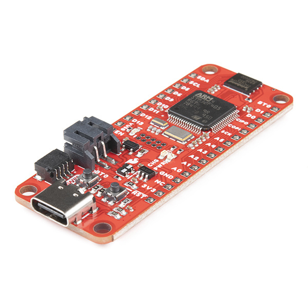
What incorporates a high-performance Arm® Cortex®-M4 32-bit RISC core, a full set of DSP instructions, memory protection unit (MPU), high-speed embedded memories, up to 4 Kbytes of backup SRAM, and an extensive range of enhanced I/Os and peripherals? The new SparkFun STM32 Thing Plus has all this and more in the popular, Feather-compatible Thing Plus form factor.
Let's have a look at the details!
Required Materials
To follow along with this tutorial, you will need the following materials. You may not need everything though depending on what you have. Add it to your cart, read through the guide, and adjust the cart as necessary.
Suggested Reading
If you aren't familiar with the Qwiic system, we recommend reading here for an overview:
| Qwiic Connect System |
We would also recommend taking a look at the following tutorials if you aren't familiar with them.
Serial Communication
I2C
ARM Programming
Hardware Overview
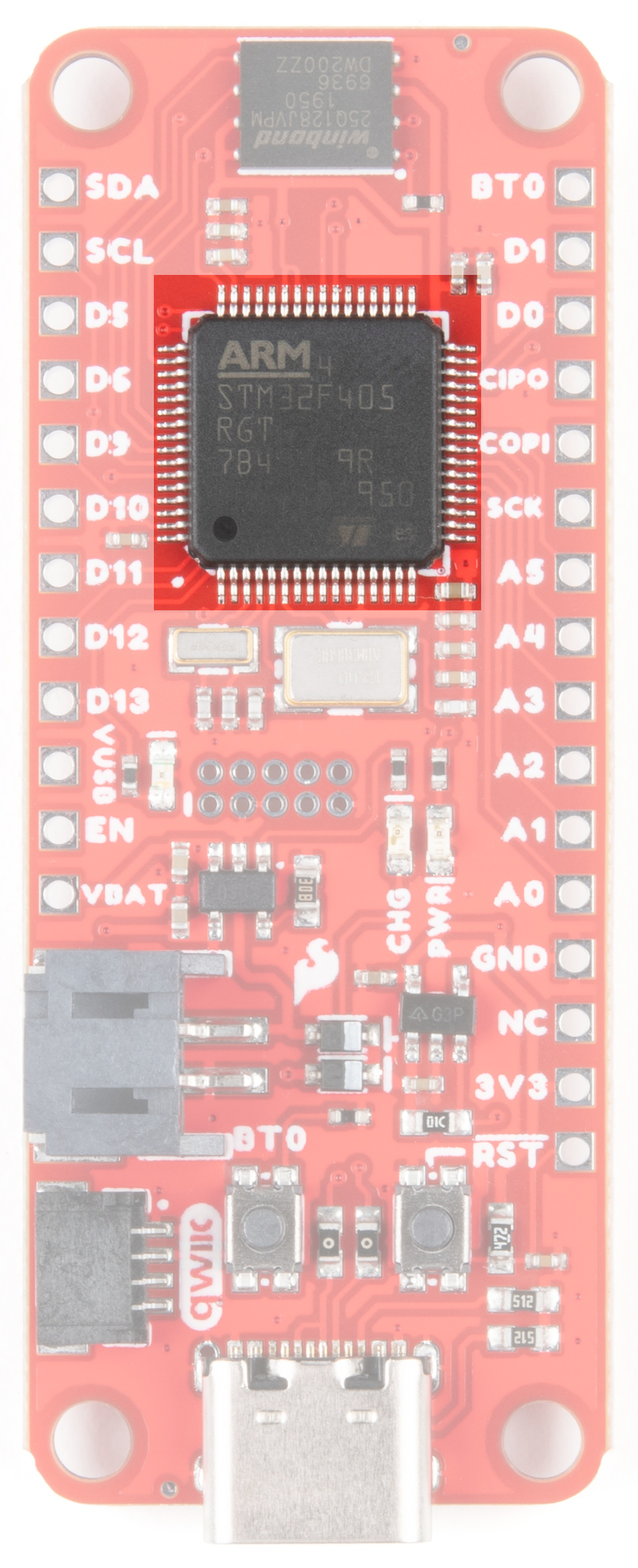
STM32F405
The STM32 Thing Plus exploits the vast capabilities of STMicroElectronics' STM32F405 series. This family of ICs uses the ARM 32-bit Cortex M4 CPU to provide high performance, floating point single precision, a full set of DSP instructions, and a memory protection unit that enhances application security. For more information, refer to the Datasheet.
Features
- Core: ARM® 32-bit Cortex®-M4 CPU with FPU
- Adaptive real-time accelerator (ART Accelerator™) allowing 0-wait state execution from Flash memory
- Frequency up to 168 MHz
- Memory protection unit
- 210 DMIPS/1.25 DMIPS/MHz (Dhrystone 2.1)
- DSP instructions
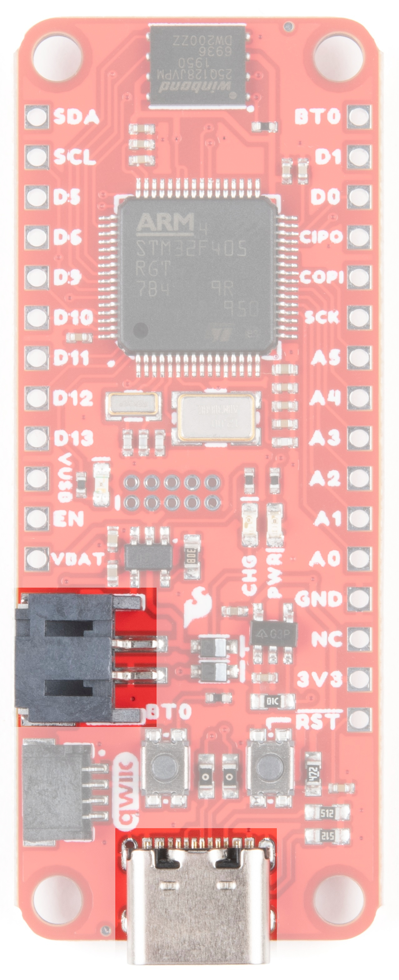
Power
Power to the STM32 Thing Plus can be supplied either by a single-cell LiPo battery or by USB-C. The STM32 Thing Plus has an onboard 3.3V regulator, as well as a LiPo battery charging circuit.
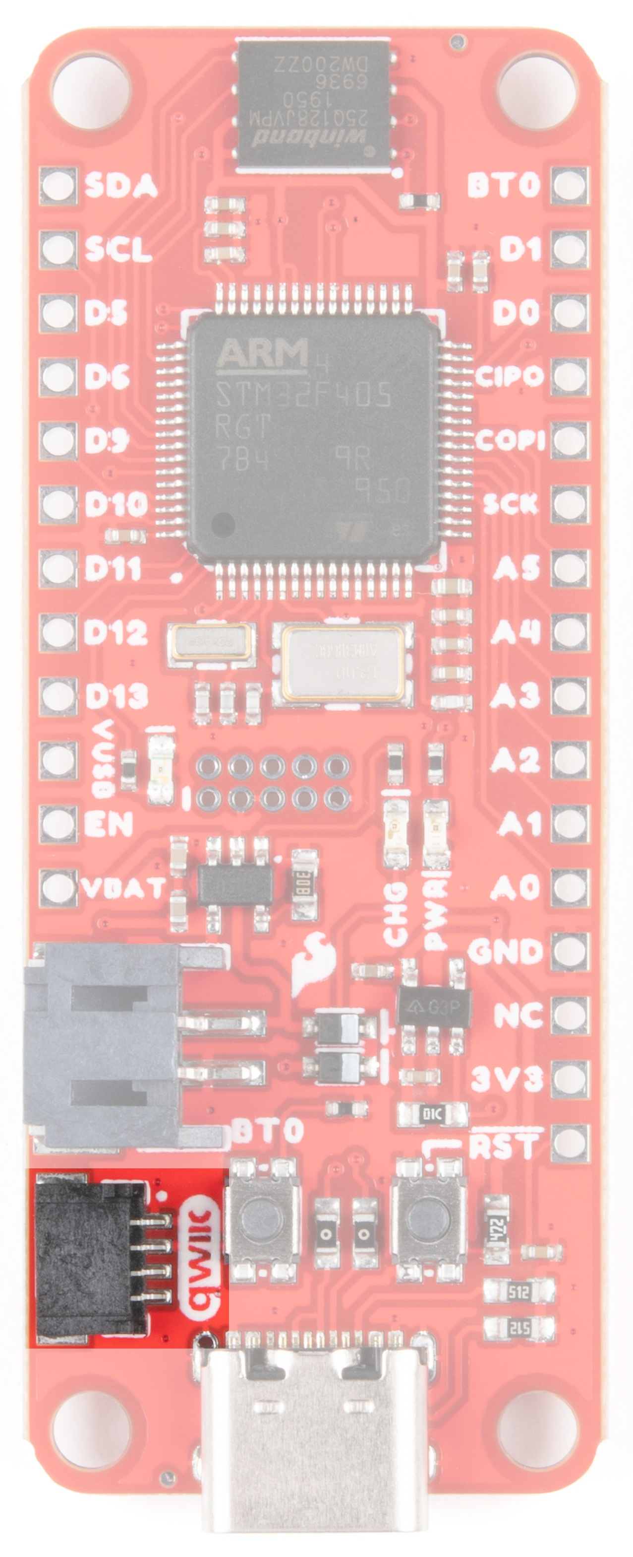
Qwiic Connector
Our Qwiic Ecosystem makes sensors pretty much plug and play. The Qwiic connector provides power and I2C connectivity simultaneously. In addition, the Thing Plus form factor breaks out the I2C functionality to PTH.
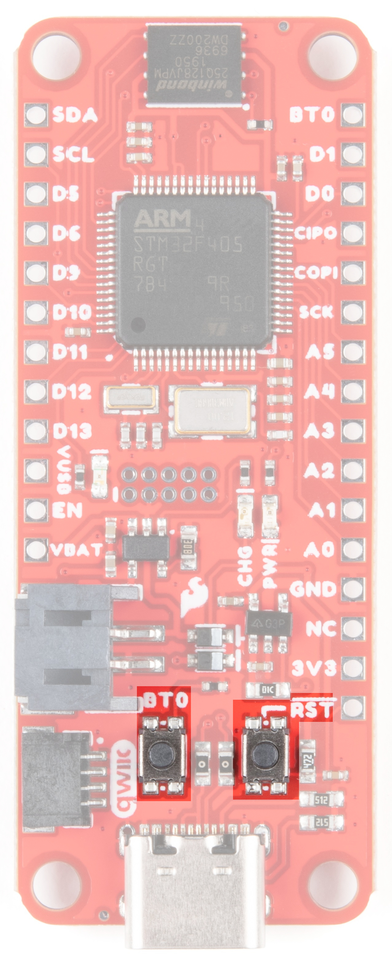
Boot and Reset Buttons
In order to upload code to the STM32 Thing Plus, you'll need these two buttons to put the board into Boot mode. To enter Boot mode, hold the Boot button down, press the Reset button (while still holding the Boot button), and then release the Boot button.
MicroSD
Want extra storage space? Add a MicroSD card using the slot on the back of the board.

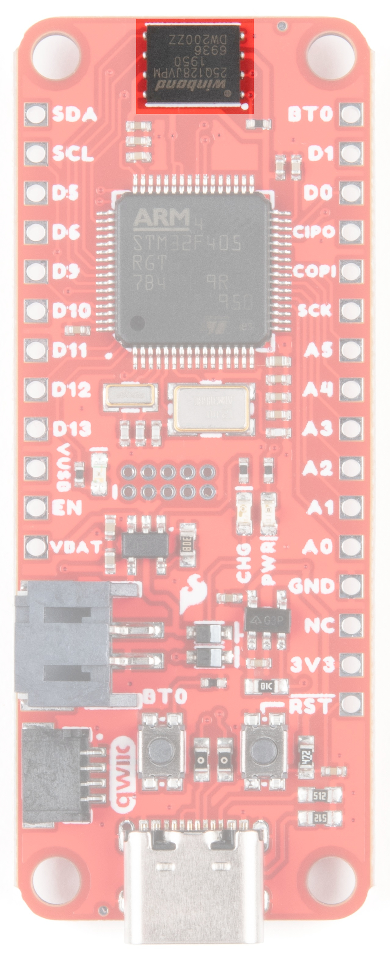
Flash
In addition to the STM32's internal Flash memory, we've provided an additional (128M-bit) Serial Flash memory.
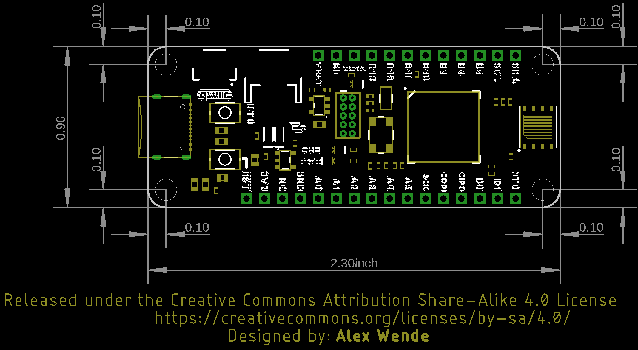
Board Dimensions
Assembly Tips
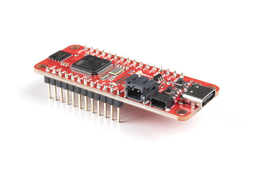
Headers
The STM32 Thing Plus ships without anything soldered into the header pins -- ensuring that you can mold the board to best fit your project. To use the chip's pins you'll need to solder something to the I/O and power rail vias broken out to either side of the board.
What you solder to the STM32 Thing Plus's I/O pins is completely up to you. The header rows are breadboard-compatible, so you may want to solder male headers in.
Then plug it into the breadboard, hanging the USB and LiPo connectors off the end, and start wiring!
Alternatively, female headers (you may need two separate strips to solder all the pins), right-angle headers, or stranded wire are all good options, depending on your project's needs.
Software Setup and Programming
Arduino Board Definition
Installation for the STM32 Thing Plus is relatively straight-forward. You will want to install the board definitions via the Arduino Boards manager. Search for SparkFun STM32 and you should see the option for the STM32 Thing Plus show up.
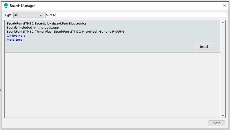
For more information on installing boards via the Arduino Board Manager, check out the add-ons section of our Installing Arduino IDE tutorial.
Installing Arduino IDE
Install STM32Cube Programmer Software
In order to work with the STM32 Thing Plus, you'll need to install the STM32Cube Programmer. This is an all-in-one multi-OS software tool for programming STM32 products. It primarily provides the driver we need, but you can also program your board using this GUI.
DFU Bootloader
As of this writing, SparkFun is using the DFU bootloader to upload code to the STM32 Thing Plus. In order to do so, you need to do the following:
- Press and hold down the Boot button
- Press and release the Reset button while continuing to press the Boot button
- Keep pressing the Boot button until the code is uploaded
Example - Blinky
With the STM32 Arduino core installed, you're ready to begin programming. If you haven't already, plug the STM32 Thing Plus into your computer using a USB-C cable.
Once the board is plugged in, it should be assigned a unique port identifier. On Windows machines, this will be something like COM#, and on Macs or Linux computers it will come in the form of /dev/tty.usbserial-XXXXXX.
Select the Board and Port
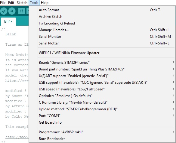
You'll notice that there are quite a few options. Make sure you have the Generic STM32F4 Series board and SparkFun Thing Plus STM32F405 board part number selected under your Tools menus.
The other options are more variable. For this example, you'll want to set your selections as you see below.
Loading Blink
To make sure your toolchain and board are properly set up, we'll upload the simplest of sketches -- Blink! The builtin LED is perfect for this test. Copy and paste the example sketch below into a fresh Arduino sketch:
language:c

void setup()
{
    pinMode(LED_BUILTIN, OUTPUT);
    Serial.begin(115200);
}

void loop()
{
    Serial.println("Hello, world!");
    digitalWrite(LED_BUILTIN, HIGH);   // turn the LED on (HIGH is the voltage level)
    delay(1000);                       // wait for a second
    digitalWrite(LED_BUILTIN, LOW);    // turn the LED off by making the voltage LOW
    delay(1000);                       // wait for a second
}
With everything setup correctly, hit the upload button.
Once the code finishes transferring, open the serial monitor and set the baud rate to 115200. You should see Hello, world!'s begin to fly by.
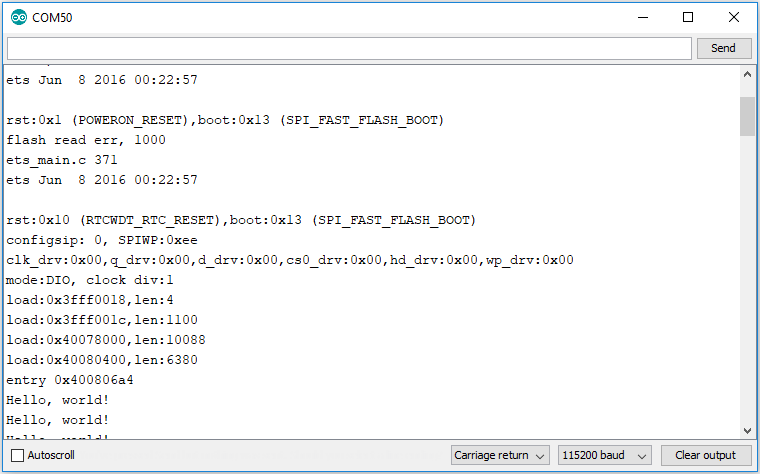
You may also notice that when the STM32 boots up it prints out a long sequence of debug messages. These are emitted every time the chip resets -- always at 115200 baud.
Example - I2C Scanner
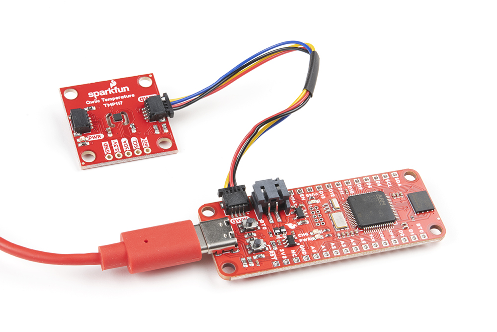
The Qwiic Connect Ecosystem makes attaching sensors a breeze. That said, sometimes it's nice to be able to scan your I2C connections to find out the address of your sensor. That's what we'll do here!
Grab your STM32 Thing Plus and attach a Qwiic Sensor to the Qwiic port on the Thing Plus like so:
Copy and paste the code below into a new Arduino sketch.
language:c
// --------------------------------------
// I2C Scanner example using Wire1
//
//
// This sketch tests the standard 7-bit addresses
// Devices with higher bit address might not be seen properly.
//

#include <Wire.h>

TwoWire Wire1(SDA1,SCL1); //Intialize Wire1 class

void setup()
{
  Wire1.begin();

  Serial.begin(115200);
  while (!Serial);             // Leonardo: wait for serial monitor
  Serial.println("\nI2C Scanner");
}


void loop()
{
  byte error, address;
  int nDevices;

  Serial.println("Scanning...");

  nDevices = 0;
  for(address = 1; address < 127; address++ )
  {
    // The i2c_scanner uses the return value of
    // the Write.endTransmisstion to see if
    // a device did acknowledge to the address.
    Wire1.beginTransmission(address);
    error = Wire1.endTransmission();

    if (error == 0)
    {
      Serial.print("I2C device found at address 0x");
      if (address<16)
        Serial.print("0");
      Serial.print(address,HEX);
      Serial.println("  !");

      nDevices++;
    }
    else if (error==4)
    {
      Serial.print("Unknown error at address 0x");
      if (address<16)
        Serial.print("0");
      Serial.println(address,HEX);
    }
  }
  if (nDevices == 0)
    Serial.println("No I2C devices found\n");
  else
    Serial.println("done\n");

  delay(5000);           // wait 5 seconds for next scan
}
Make sure your options are all set up correctly in the Tools menu, and make sure you put the Carrier Board into Boot Mode in order to upload the code.
- Press and hold down the Boot button
- Press and release the Reset button while continuing to press the Boot button
- Release the Boot button and press the Upload button in your Arduino IDE
After uploading, open the Serial Monitor and set the baud to 115200. You should see something similar to the printout below.
Example - Serial UART
Let's have a quick look at an example using UART. If you're unfamiliar with Serial Output, go ahead and have a look at our Serial Basic Tutorial.
Grab your MicroMod STM32 Thing Plus board and attach the Serial Basic Rx and Tx pins like so:
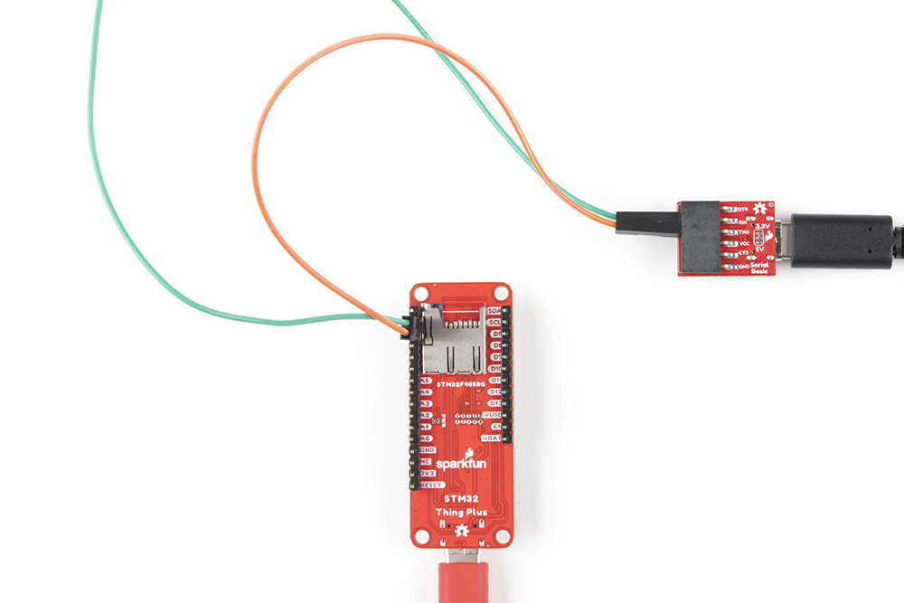
Note that the RX pin functionality is D0 and the TX pin functionality is D1.
Copy and paste the code below into a new Arduino sketch.
language:c
// --------------------------------------
// UART example using Serial1
//
//
// This sketch prints "Hello World!" every second
// using the secondary UART pins D0 and D1.
//


HardwareSerial Serial1(D0, D1); //Attach Serial1 to D0 and D1

void setup() {
  Serial1.begin(115200);
  while (!Serial1) {
    ; // wait for serial port to connect. Needed for Native USB only
  }
  Serial1.println("Goodnight moon!");

}

void loop() {
  Serial1.println("Hello World!");
  delay(1000);
}
Make sure your options are all set up correctly in the Tools menu, and make sure you put your board into Boot Mode in order to upload the code.
- Press and hold down the Boot button
- Press and release the Reset button while continuing to press the Boot button
- Release the Boot button and press the Upload button in your Arduino IDE
Once your code is uploaded, open up the Serial Monitor attached to your Serial Basic with the baud set to 115200 to see your output!
Troubleshooting
If you need technical assistance and more information on a product that is not working as you expected, we recommend heading on over to the SparkFun Technical Assistance page for some initial troubleshooting.
If you don't find what you need there, the SparkFun Forums are a great place to find and ask for help. If this is your first visit, you'll need to create a Forum Account to search product forums and post questions.
Resources and Going Further
This should get you started with the STM32 Thing Plus. Need more information? Check out some of the links below:
Check out these other great Thing Plus tutorials from SparkFun: