SparkFun Serial Basic CH340C Hookup Guide
 Elias The Sparkiest
Serial Basic Overview
The pinout of the Serial Basic mimics the common DTR/RX/TX/VCC/CTS/GND pinout found on hundreds of FTDI-to-USB derivatives.
| Pin Label | Input/Output | Description |
|---|---|---|
| DTR | Output | Data Terminal Ready, Active Low |
| RXI | Input | Serial Receive |
| TXO | Output | Serial Transmit |
| VCC | Supply Output | Power supply 3.3V (Default) or 5V |
| CTS | Input | Clear To Send, Active Low |
| GND | Supply Output | Ground (0V) supply |
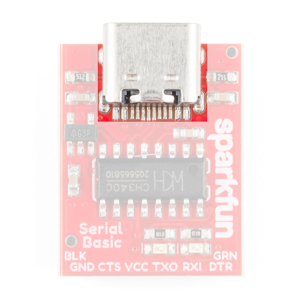
USB-C
USB-C gives you the potential of more power than the previous generation of USB. USB-C is used to power everything from laptops to low powered micro controllers and has the amazing capability of being reversible.
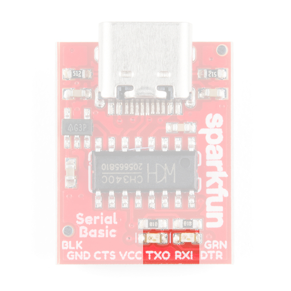
LEDs
The two LEDs on the board are connected to TX (Green) and RX (Yellow) and are correctly aligned to the silk header labels: RXI and TXO . This is a quick and handy way to see the serial traffic.
Alignment Markers
The GRN and BLK silk in the corners opposite of the USB-C connector, is there to help you align the board properly with products that use these same orientation indicators.
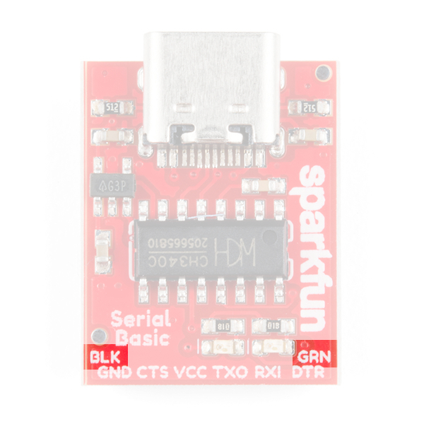
The Serial Basic mates seamlessly with products that use the standard serial connection. If you see a board with the BLK and GRN labels, then you know it will be compatible with the Serial Basic.

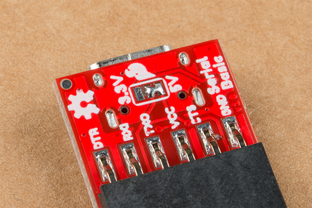
Voltage Selection Jumper
There is a jumper on the underside of the board that controls the output voltage on the VCC pin. By default, the board outputs 3.3V and has 3.3V signals.
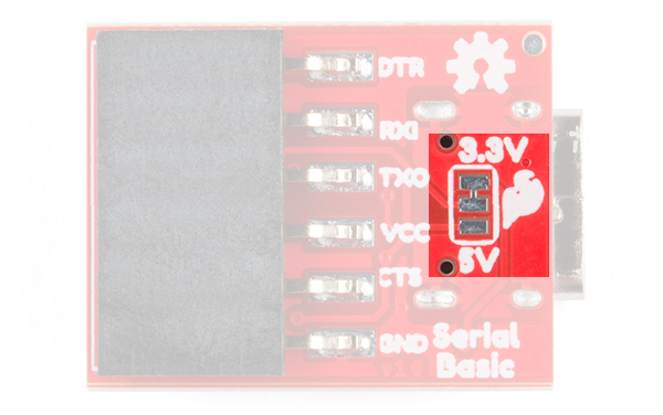
3.3V. When the jumper is set to 3.3V, the board uses an on board 3.3V regulator capable of sourcing 600mA. If you attempt to pull more than 600mA, the regulator will go into short-circuit shutdown where it will only output 150mA.
You can change the board's output and signal to 5V by cutting the trace between the center and 3.3V labeled pad and putting solder on the center and 5V labeled pad. This will change the board's output to 5V on the VCC pin with 5V signals.
When the jumper is set to 5V, the board will source as much power as your USB port will provide. With USB-C this can be up to 1.5Amps but depending on what is providing the power and the capabilities of your cable, you can get up to 3 Amps.