SparkFun Qwiic MicroPressure Hookup Guide
Hardware Overview
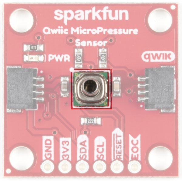
Micro pressure sensor MPR
Honeywell's MPR Series MPRLS0025PA00001A sensor is a very small piezoresistive silicone pressure sensor offering I2C ready digital output for reading pressure over the specified full scale pressure span and temperature range. The sensor itself measures 5 mm x 5 mm and has a calibrated pressure sensing range from 1-25 PSI. It is compatible with a variety of liquid media, has a compensated temperature range of 0ºC to 50ºC (32ºF to 122ºF), and has a total error band after customer autozero as low as ±1.25 %FSS. For more information on this little guy, head on over to the datasheet.
Power
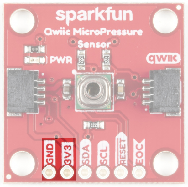
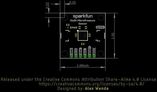
Ideally, power will be supplied via the Qwiic connectors on either side of the board. Alternatively, power can be supplied through the header along the bottom side of the board labeled 3V3 and GND. The input voltage range should be between 1.8-3.6V.
Qwiic Connectors
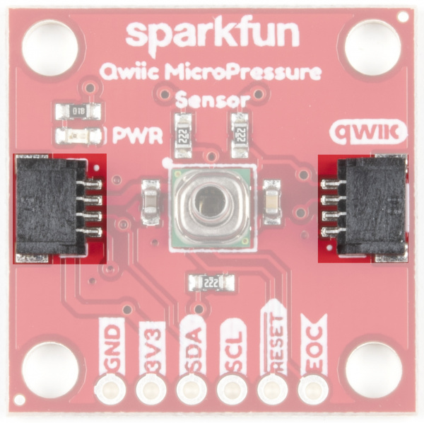
Our Qwiic Ecosystem makes sensors pretty much plug and play. There are two Qwiic connectors on either side of the Qwiic MicroPressure Sensor board to provide power and I2C connectivity simultaneously.
I2C Pins
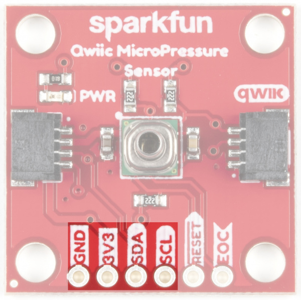
The I2C pins break out the functionality of the Qwiic connectors. Depending on your application, you can connect to these pins via the plated through holes for SDA and SCL.
Reset and EOC Pins
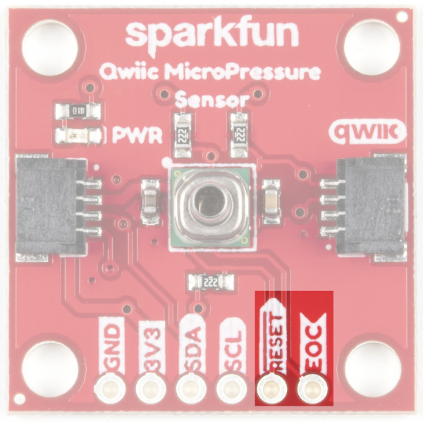
The reset pin is active low, with an external 2.2 kΩ pull-up resistor on board. While not needed for the board to work, this pin can be pulled low externally to reset the sensor.
The EOC, or End Of Conversion, pin is set high when a measurement and calculation have been completed and the data is ready to be clocked out. Alternatively the status register of the sensor can also be used to check to see when a new measurement is ready.
Power LED
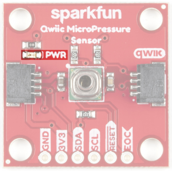
Located towards the top left of the board, the Power LED gives you visual confirmation that your board is powered and ready to go.
Jumpers
I2C Jumpers
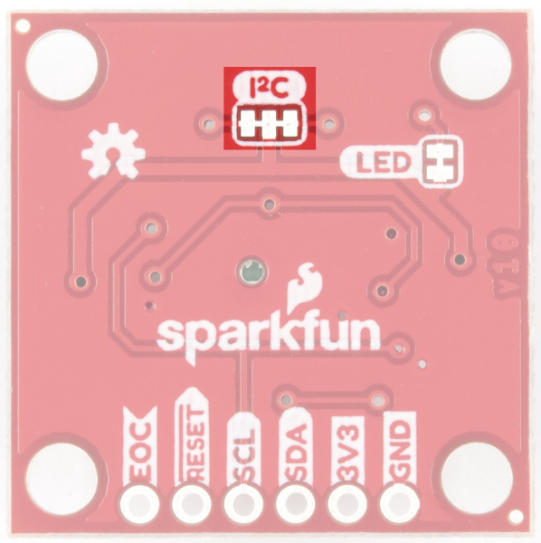
Like our other Qwiic boards, the Qwiic MicroPressure Sensor comes equipped with pull-up resistors on the clock and data pins. If you are daisy-chaining multiple Qwiic devices, you will want to cut this jumper; if multiple sensors are connected to the bus with the pull-up resistors enabled, the parallel equivalent resistance will create too strong of a pull-up for the bus to operate correctly. As a general rule of thumb, disable all but one pair of pull-up resistors if multiple devices are connected to the bus. To disable the pull up resistors, use an X-acto knife to cut the joint between the two jumper pads highlighted below.
LED Jumper
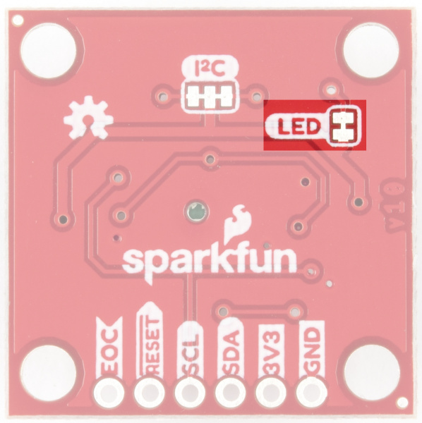
If power consumption is an issue, cutting this jumper will disable the Power LED on the front of the board.
