SparkFun Qwiic Digital Temperature Sensor - TMP102 Hookup Guide
 Alex the Giant, Ell C
Hardware Overview
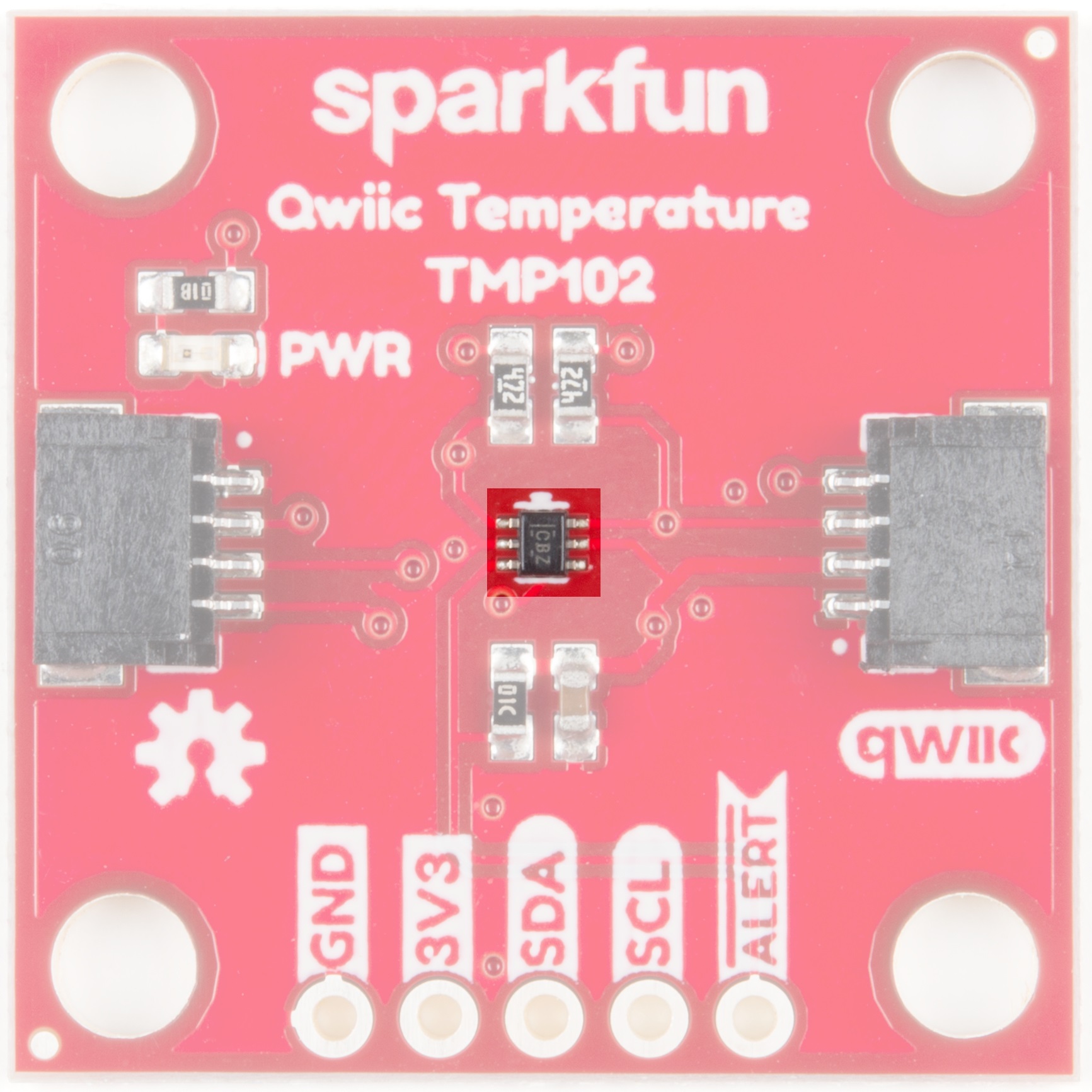
TMP102
Have you heard the phrase "Good things come in small packages"? Well, here's is a prime example! This board centers around Texas Instruments' TMP102 Low-Power Digital Temperature Sensor. This tiny little chip measures 1.6-mm × 1.6-mm and packs quite a nice punch. Here are some of the highlights, but feel free to check out the Datasheet for more information.
Highlights:
- Uses the I2C interface
- 12-bit, 0.0625°C resolution
- Typical temperature accuracy of ±0.5°C
- Supports up to four TMP102 sensors on the I2C bus at a time
Power
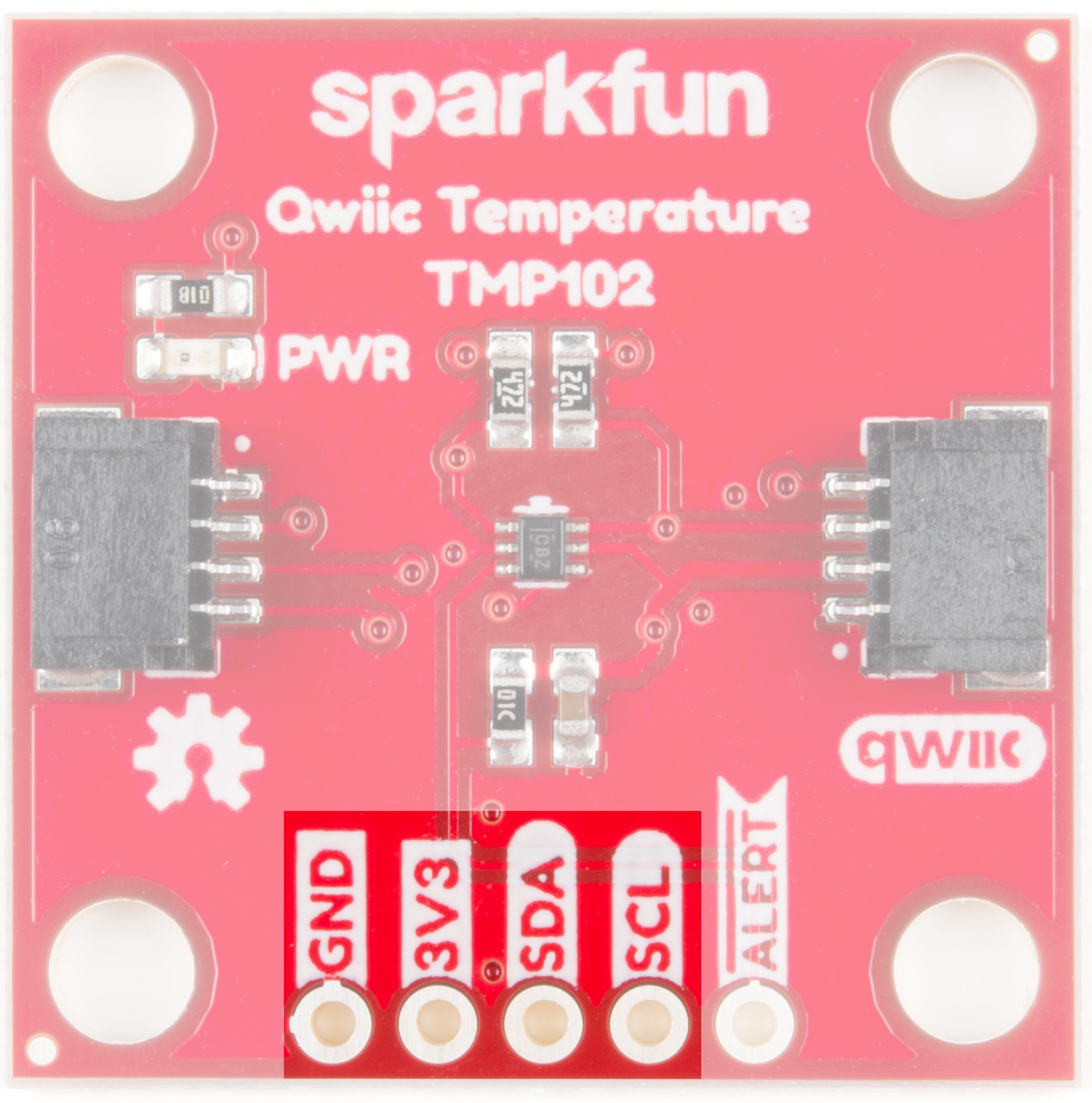
Ideally, power will be supplied via the Qwiic connectors on either side of the board. Alternatively, power can be supplied through the header along the bottom side of the board labeled 3V3 and GND. The input voltage range should be between 1.4-3.6V.

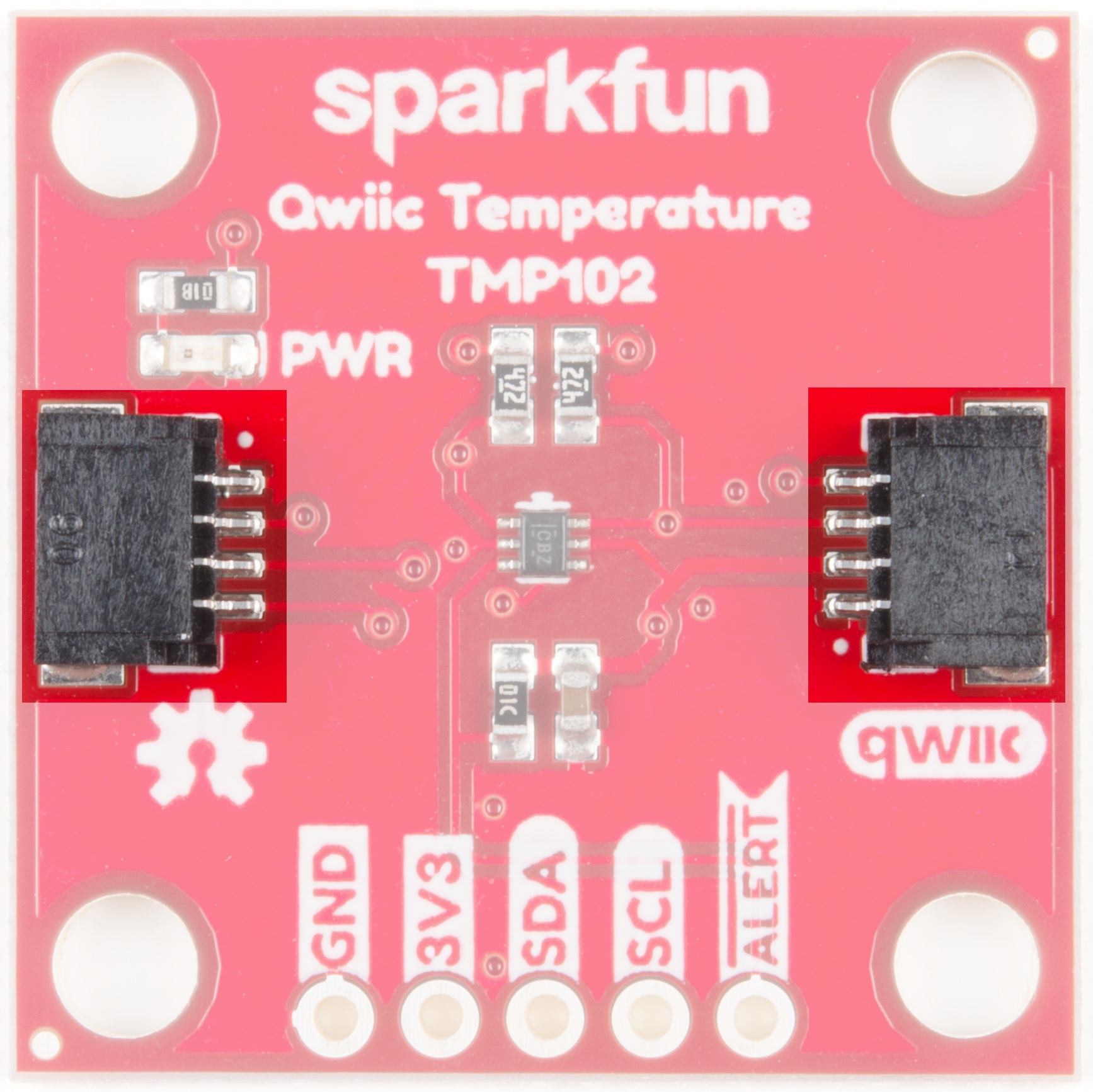
Qwiic Connectors
Our Qwiic Ecosystem makes sensors pretty much plug and play. There are two Qwiic connectors on either side of the Qwiic Temperature Sensor - TMP102 board to provide power and I2C connectivity simultaneously.
The I2C address of the board is 0x48 by default , but has 3 other addresses the board can be configured to use.
I2C Pins
The I2C pins break out the functionality of the Qwiic connectors. Depending on your application, you can connect to these pins via the plated through holes for SDA and SCL.
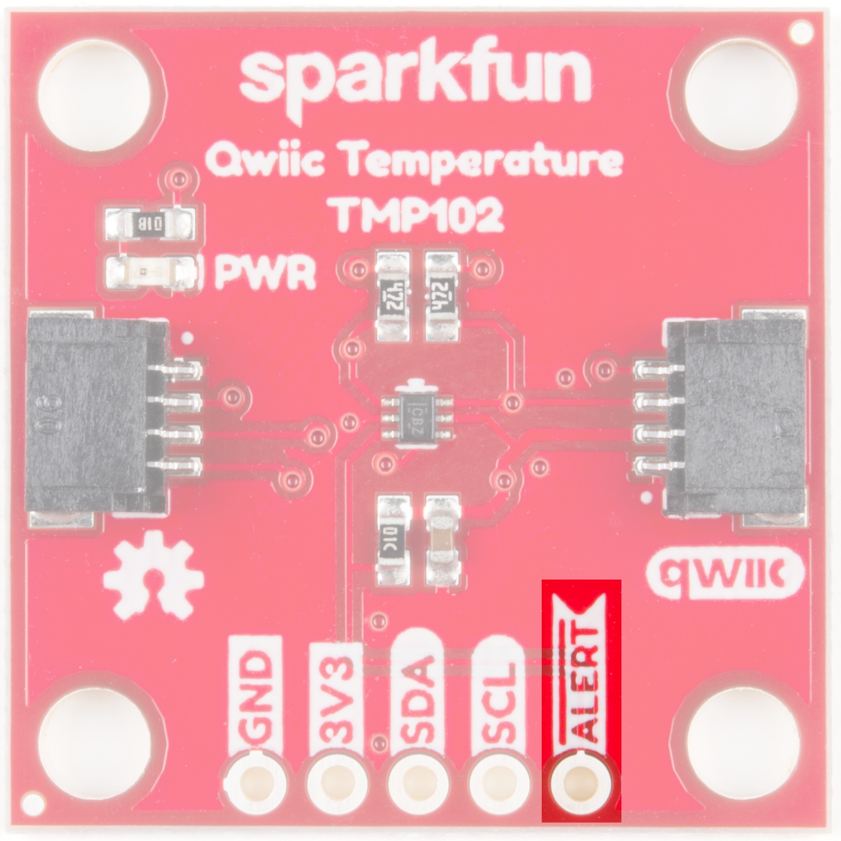
Alert Pin
The alert pin is an over temperature alert, which has an open-drain and is pulled up through a 10kΩ resistor. The alert can also be read over I2C as shown in the example in the Software Setup and Programming section.
Jumpers
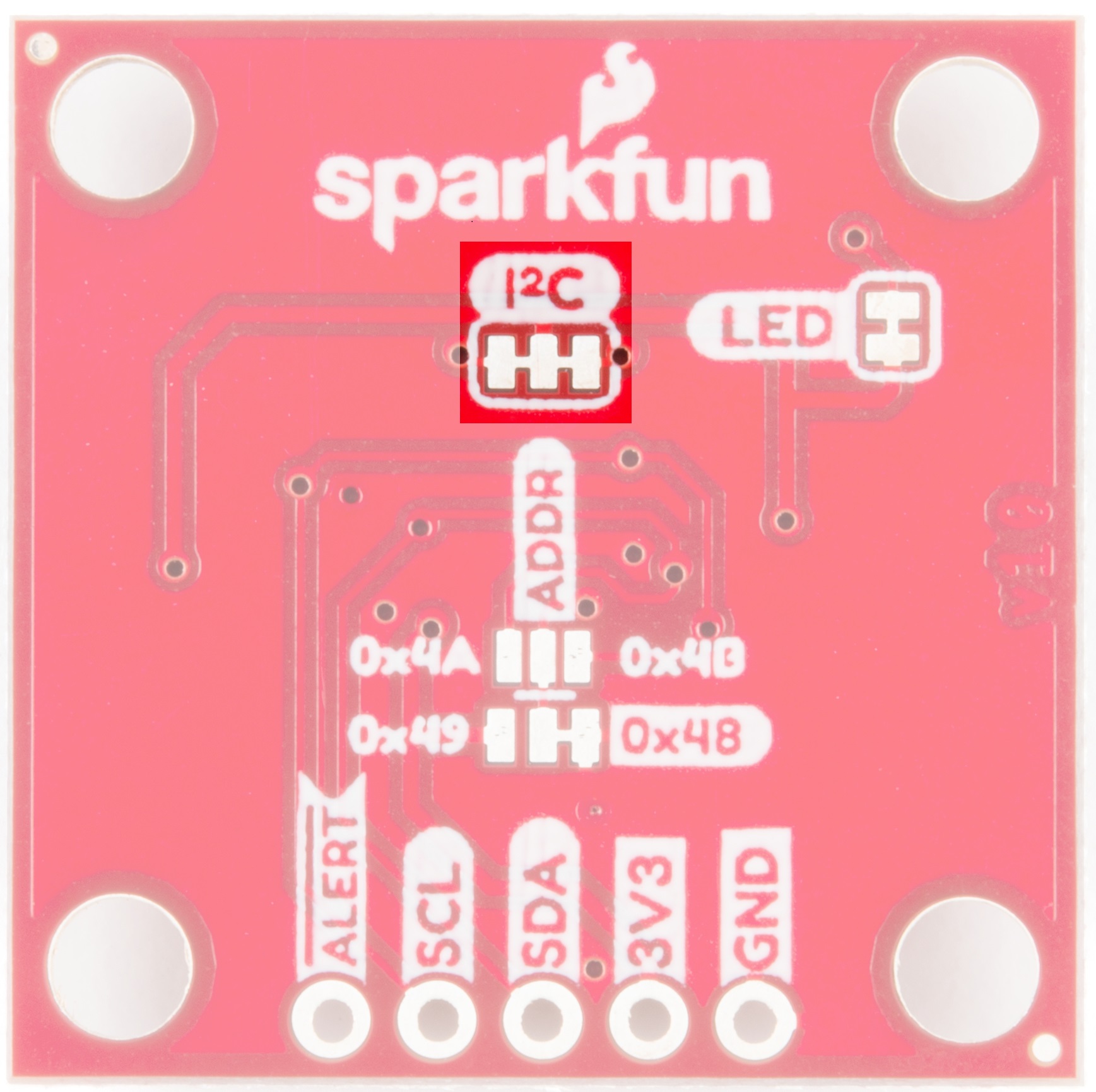
I2C Jumpers
Like most (if not all) of our Qwiic boards, the TMP102 Temperature Sensor comes equipped with a pull-up resistor. If you are daisy-chaining multiple Qwiic devices, you will want to cut this jumper; if multiple sensors are connected to the bus with the pull-up resistors enabled, the parallel equivalent resistance will create too strong of a pull-up for the bus to operate correctly. As a general rule of thumb, disable all but one pair of pull-up resistors if multiple devices are connected to the bus. To disable the pull up resistors, use an X-acto knife to cut the joint between the two jumper pads highlighted below.
ADDR Jumpers
The default I2C address of the board is 0x48. To change the address, cut the jumper connecting the two pads closest to the 0x48 label. Soldering one of the center pads to one of the outer most pads will change the boards address to the matching label. The TMP102's address is determined by connecting the address pin directly to one of the following:
| ADDR | Address |
|---|---|
| GND | 0x48 |
| 3V3 | 0x49 |
| SDA | 0x4A |
| SCL | 0x4B |

LED Jumpers
Cutting this jumper will disable the Power LED on the front of the board.

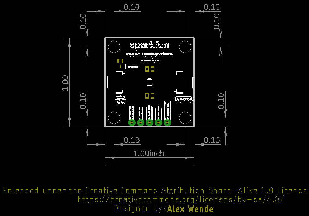
Board Dimensions