$48.95
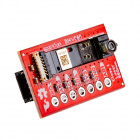
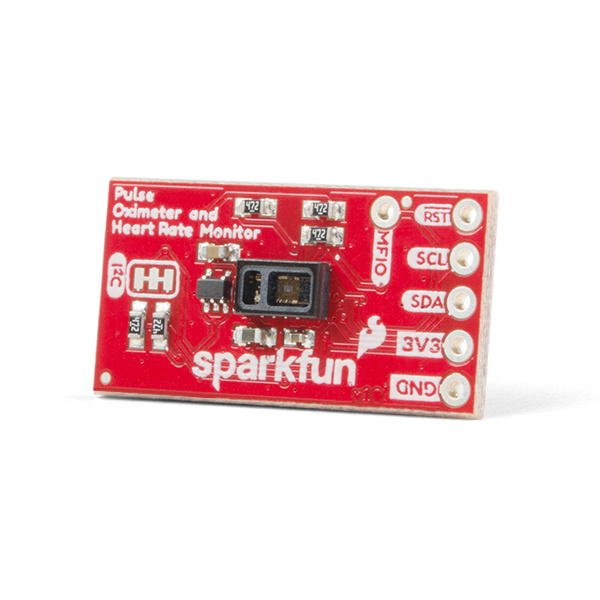
The SparkFun Pulse Oximeter and Heart Rate Monitor is an I²C based biometric sensor. Utilizing two chips from Maxim Integrated, the SparkFun Pulse Oximeter and Heart Rate Monitor has both the MAX30101 biometric sensor and MAX32664 biometric hub. While the former does all the sensing, the latter is an incredibly small and fast Cortex M4 processor that handles all of the algorithmic calculations, digital filtering, pressure/position compensation, advanced R-wave detection and automatic gain control. We've combined them and written an Arduino Library with example code demonstrating basic to advanced features to help get you started utilizing the SparkFun Pulse Oximeter and Heart Rate Monitor into your next project. Or if you're looking to put these IC's into a final product, Maxim has provided some features to get FDA approval. Let's get started!
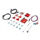
To follow along with the example code used in this tutorial, you will also need the following materials. You may not need everything though depending on what you have. Add it to your cart, read through the guide, and adjust the cart as necessary.

If you need different size Qwiic cables, we offer a kit that contains many sizes but we also carry them individually as well. Make sure to use a Qwiic cable of sufficient length for flexibility. Short lengths like the 50mm Qwiic cable can be harder to obtain sensor readings.

Our Qwiic ecosystem keeps growing and growing with a host of new Qwiic enabled micro-controllers and sensors, check here for an overview.
We would also recommend taking a look at the following tutorials if you aren't familiar with them.
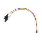
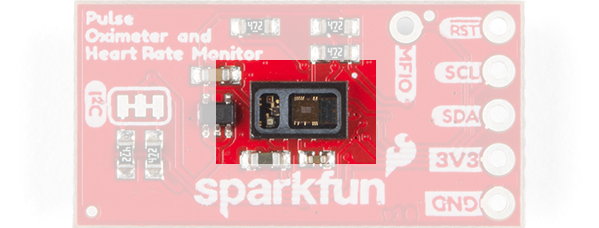
You can provide 3.3V through the Qwiic connector on the "MAX32664 Side" of the board or through the 3V3 and GND labeled pins on the through hole header.
 |
 |
| MAX30101 Side | MAX32664 Side |
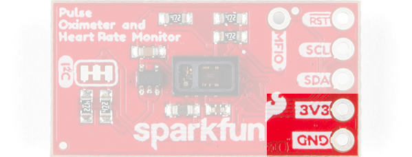
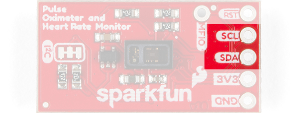
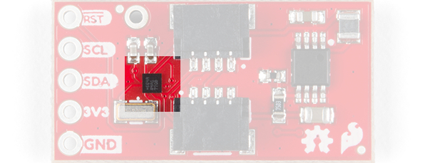
There are two Qwiic connectors on the board to easily get data from the sensor via I²C. Another option is to solder directly to the I²C plated through holes on the side of the board. Unfortunately, this board requires additional pins to function, see section below Additional Required pins.
 |
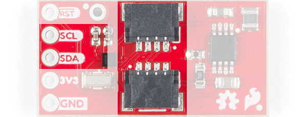 |
| MAX30101 Side | MAX32664 Side |
We have many Qwiic sensors and Qwiic enabled microcontrollers. Check out our Qwiic Ecosystem page to get a glimpse of what else we have to offer.
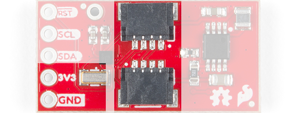
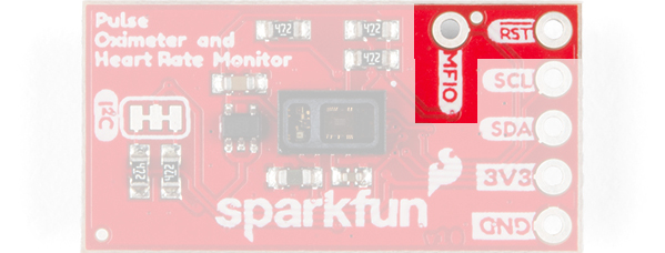
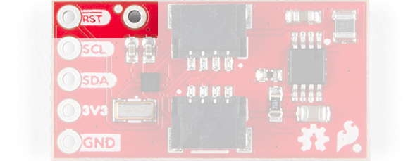
This board has two additional pins on it's header: the RESET and MFIO pin. These pins are required for the board to function because they determine if the board enters data collection mode or not. The Hardware Hookup section below will walk you through how to connect this board properly.
 |
 |
| MAX30101 Side | MAX32664 Side |
The MAX30101 gets your heart rate (BPM) and blood oxygen levels (SpO2) through the process of photoplethysmography, which is the process of obtaining the aforementioned biometric data with light. The SparkFun Pulse Oximeter works by placing your finger gently on the sensor in which it shines red, infrared, and sometimes green light through your skin. The capillaries filled with blood under your skin will absorb this light, or not, and the MAX30101 sensor will read which light comes back. This light data will then be sent back to the Biometric Sensor Hub which handles all the calculations to determine heart rate and blood oxygen levels. Simple right?!
The MAX32664 Biometric Sensor Hub is a very small Cortex M4 micro-controller dedicated to receiving the data it receives from the MAX30101 and running the calculations to determine heart rate and blood oxygen. When you're interfacing with the SparkFun Pulse Oximteter and Heart Rate Monitor, you are in effect interfacing with this wicked fast microcontroller. There are a multitude of settings to tailor the sensor to the persons you'll be monitoring made available through the Arduino Library we've written for it. Check the Arduino Examples below for more info!
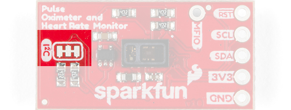
There a single set of jumpers on the MAX30101 side (non Qwiic connector side) of this product. This triple jumper labeled I2C connects pull-up resistors to the I²C data lines. If you're daisy chaining many I²C devices together, you may need to consider cutting these traces.
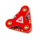
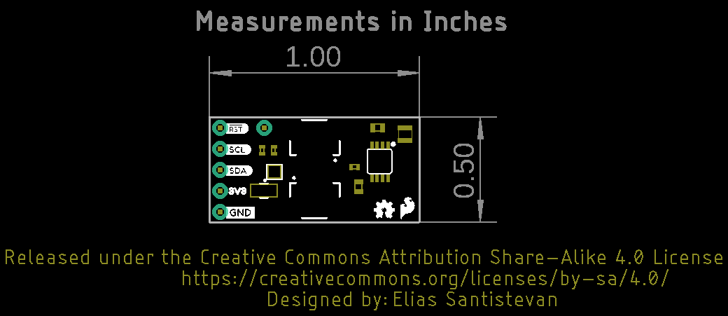
This board is very small, measuring at 1.00in x 0.5in (25.4mm x 12.7mm), which means it will fit nicely on your finger without all the bulk.
MFIO and RESET.
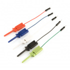
This board is an I²C based board and so we've included a Qwiic Connector. However, it isn't a "pure" Qwiic board as it requires two additional pins to be attached in order for it to function. However, you still don't need to solder if you have some of our IC hook with pigtail and in fact that's what I'll use for the following example. First, let's plug in our Qwiic Connector cable to either of the Qwiic connectors on the SparkFun Pulse Oximeter and Heart Rate Monitor.
Next we'll take the IC hooks and plug them into Redboard Qwiic into pins 5 and 4.
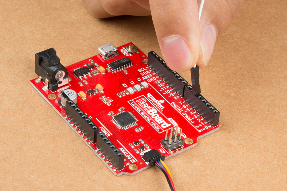
We'll then attach the claw side of the the IC hooks, the first in pin 5 to MFIO and the second plugged into pin 4 to RESET.
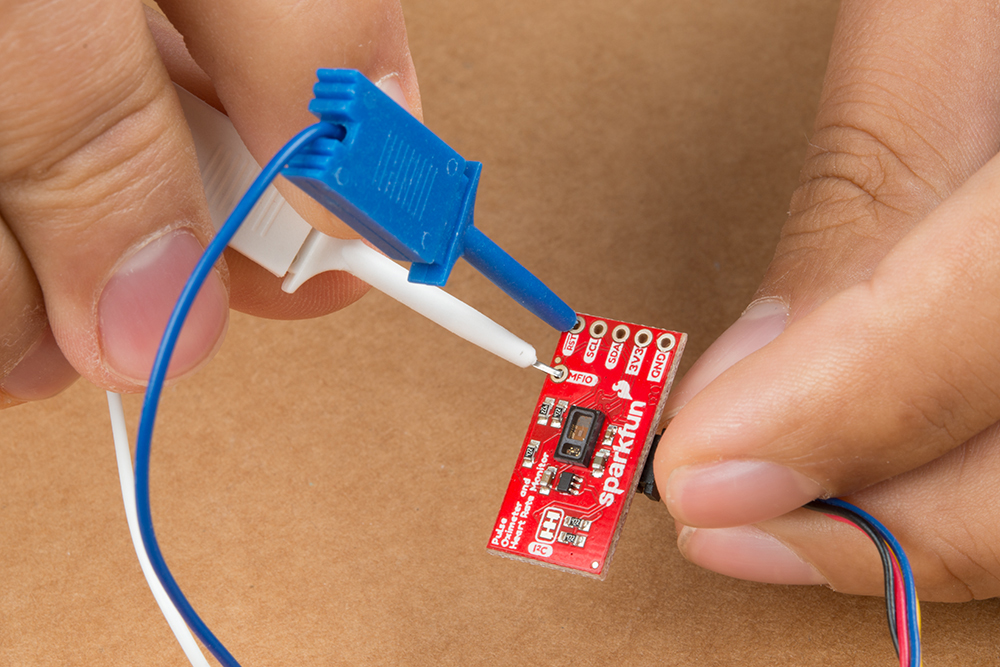
When we get to sensing your pulse and blood oxygen levels, it's important that when you place your finger onto the sensor that you place it lightly and with consistent pressure. You can try to do this without any support, but I found that a rubber band is a good place to start.

We've written an Arduino library to make it even easier to get started with the SparkFun Pulse Oximeter and Heart Rate Monitor. The library will give you the full functionality of the sensor and provides example code to get the most our of your project. You can obtain these libraries through the Arduino Library Manager by searching SparkFun Bio Sensor Arduino Library. The second option is to download the ZIP file below from its GitHub repository to manually install it.
This section shows some of the sensor's settings in clear tables so that you don't have to run to the datasheet for reference. It will also help to expand upon some unique characteristics of the SparkFun Bio Sensor Hub Library. Feel free to move beyond this section and jump to the Example Section below until this information becomes relevant in one of the examples.
As you'll see below, the library uses a type that is unique to the SparkFun Pulse Oximeter and Heart Rate Monitor. The name of this type is bioData and with it we'll be able to get at the biometric data that comes out of the board. Below is a table that shows all of the possible data stored within this mysterious new container, it has been named body for the table below and the following examples.
| bioData Members | Information Provided |
|---|---|
| body.heartrate | Heart rate |
| body.oxygen | Blood Oxygen Levels |
| body.confidence | The Sensor's confidence in the reported data. |
| body.status | Finger Detection |
| body.irLed | Number of IR LED Samples |
| body.redLED | Number of Red LED Samples |
In addition to the information above, mode 2 also gives the following two data points.
| bioData Members | Information Provided |
|---|---|
| body.rValue | Sp02 r Value |
| body.extStatus | Extended Finger Status Message |
Below is a reference table for the body.status member which tells you if the sensor has detected a finger or some other object that is not a finger. It relays this information with four numbers: 0-3.
| Status Number | Description |
|---|---|
| 0 | No Object Detected |
| 1 | Object Detected |
| 2 | Object Other Than Finger Detected |
| 3 | Finger Detected |
Below is a reference table for the body.exStatus member which is an expansion of the first finger status messaging. This is enabled in mode 2 and contains 8 different values.
| Status Number | Description |
|---|---|
| 0 | Success |
| 1 | Not Ready |
| -1 | Object Detected |
| -2 | Excessive Sensor Device Motion |
| -3 | No object detected |
| -4 | Pressing too hard |
| -5 | Object other than finger detected |
| -6 | Excessive finger motion |
There is trade off between higher resolution (i.e. longer pulse width) and the number of samples that you can collect per second. The table below shows how the resolution and sample rate interact.
| Samples/Second | Pulse Width (uS) | |||
|---|---|---|---|---|
| 69 | 118 | 215 | 411 | |
| 50 | O | O | O | O |
| 100 | O | O | O | O |
| 200 | O | O | O | O |
| 400 | O | O | O | O |
| 800 | O | O | O | |
| 1000 | O | O | ||
| 1600 | O | |||
| Resolution (bits) | 15 | 16 | 17 | 18 |
In this first example, we'll read the heart rate and and blood oxygen level of the person we're monitoring. We'll also look at two other important values that the SparkFun Pulse Oximeter and Heart Rate Monitor provides so that you can ascertain whether the heart rate is accurate and whether a finger is being detected. Open the example up by heading to File > Examples > SparkFun Bio Sensor Hub Library > Example1_config_BPM_Mode1.ino .
Let's start at the top of Example 1: Config BPM Mode 1. Of note here, is that when we create an instance of the library called bioHub, we provide the SparkFun Pulse Oximeter's address but also the pin numbers used on the Arduino that the the RESET and MFIO are attached to: pin 4 and 5 respectively. These pins are necessary for the board's function, so make sure they're included here and also put in the correct order: RESET then MFIO pin.
language:c
#include <SparkFun_Bio_Sensor_Hub_Library.h>
#include <Wire.h>

// No other Address options.
#define DEF_ADDR 0x55

// Reset pin, MFIO pin
const int resPin = 4;
const int mfioPin = 5;

// Takes address, reset pin, and MFIO pin.
SparkFun_Bio_Sensor_Hub bioHub(resPin, mfioPin);

bioData body;
Just above you'll see this funky type called bioData. This is a type that is unique to the SparkFun Pulse Oximeter and Heart Rate Monitor and it holds all the Biometric data of the sensor: Heart rate, confidence, blood oxygen levels, finger detection, led data, etc. I've provided a table just above that describes all the available information that it holds (see Reference Tables and Sensor Settings). Later in the example, we'll see how it's used.
Next let's look at the setup. There are two functions to point out. First, the bioHub.begin() function call makes sure that we can communicate with the sensor. Secondly and equally as important bioHub.configBPM(MODE_ONE), configures the SparkFun Pulse Oximeter's settings and enables all of the necessary algorithms within the sensor to begin collecting data. Which data is collected depends on how the sensor is configured. You'll get biometric data with bioHub.configBPM(), you can just get LED data with bioHub.configSensor(), or you can get all the data with bioHub.configSensorBPM(). As soon as this is called, the sensor will begin collecting data. However, the sensor lags a couple of seconds behind when it begins sensing the data and when it actually gives that data to the user. I've put a four second delay at the end of setup to give some time for the data to catch up.
language:c
void setup(){

  Serial.begin(115200);

  Wire.begin();
  int result = bioHub.begin();
  if (!result)
    Serial.println("Sensor started!");
  else
    Serial.println("Could not communicate with the sensor!!!");

  Serial.println("Configuring Sensor....");
  int error = bioHub.configBpm(MODE_ONE); // Configuring just the BPM settings.
  if(!error){
    Serial.println("Sensor configured.");
  }
  else {
    Serial.println("Error configuring sensor.");
    Serial.print("Error: ");
    Serial.println(error);
  }
  // Data lags a bit behind the sensor, if you're finger is on the sensor when
  // it's being configured this delay will give some time for the data to catch
  // up.
  delay(4000);

}
In the main loop, the biometric data is collected from the SparkFun Pulse Oximeter and Heart Rate Monitor with the function bioHub.readBpm(), and it's saved to body. Now to get at that information, we call body.heartrate, body.oxygen, etc. Easy!
language:c
void loop(){

    // Information from the readBpm function will be saved to our "body"
    // variable.
    body = bioHub.readBpm();
    Serial.print("Heartrate: ");
    Serial.println(body.heartRate);
    Serial.print("Confidence: ");
    Serial.println(body.confidence);
    Serial.print("Oxygen: ");
    Serial.println(body.oxygen);
    Serial.print("Status: ");
    Serial.println(body.status);
    delay(250); // Slowing it down, we don't need to break our necks here.
}
A note on body.confidence and body.status. The confidence level is the sensor's confidence in the heart rate that was reported. The status is whether or not the sensor has detected a finger. See the table above for the four possible status numbers and what they mean.
As opposed to Example 1, In Example 2's setup, we give the argument MODE_TWO to bioHub.configBPM() to get more information from the SparkFun Pulse Oximeter and Heart Rate Monitor. Specifically we'll get an extended finger status and the R value of the blood oxygen data.
language:c
Serial.println("Configuring Sensor....");
int error = bioHub.configBpm(MODE_TWO); // Configuring just the BPM settings.
if(!error){
    Serial.println("Sensor configured.");
}
else {
    Serial.println("Error configuring sensor.");
    Serial.print("Error: ");
    Serial.println(error);
}
Simple right? Nothing else changes except that when we pull the data we now have access to more data: body.extStatus and body.rValue.
language:c
void loop(){

    // Information from the readBpm function will be saved to our "body"
    // variable.
    body = bioHub.readBpm();
    Serial.print("Heartrate: ");
    Serial.println(body.heartRate);
    Serial.print("Confidence: ");
    Serial.println(body.confidence);
    Serial.print("Oxygen: ");
    Serial.println(body.oxygen);
    Serial.print("Status: ");
    Serial.println(body.status);
    Serial.print("Extended Status: ");
    Serial.println(body.extStatus);
    Serial.print("Blood Oxygen R value: ");
    Serial.println(body.rValue);
    delay(250); // Slowing it down, we don't need to break our necks here.
}
Check the reference table above under Finger Status for more information on what each number means, there are eight. The R value refers to a correlation coefficient used to determine a statistical relationship between two variables: blood oxygen and a optical plate placed over the sensor. This does not refer to the glass shield on the sensor but rather a shield that would be placed over the sensor if you decided to implement this into a final product. In other words the company that manufactures this IC, Maxim Integrated has given the user a way to get faster FDA approval when using this IC in a final product. You can read more about that here. For those of us just tinkering in a project it has no Real value. Get it?
I won't break down this example code because you have all the necessary tools to get you started with the SparkFun Pulse Oximeter and Heart Rate Monitor. However, there are a few more settings to fine tune the Automatic Gain Control (AGC) algorithm that the MAX32664 Sensor uses to automatically adjust the MAX30101 on the fly. This particular algorithm is being used in the first example because it's turned on automatically with the configBPM() function call. Configuring the sensor to give both sensor and biometric data (configSensorBpm()) does not have this algorithm enabled and so relies on the default settings of the MAX30101 sensor, unless of course you have configured the pulse width and sample collection yourself. In Example 4 we talk about how to modify these values.
The fourth example will show you how to adjust the accuracy of the SparkFun Pulse Oximeter and Heart Rate Monitor. We'll do this by adjusting the length of time that the LEDs inside the MAX30101 pulse, which will also impact how many samples we can get at a time. So we'll talk about these two settings and how they play against each other. Open the example up by heading to File > Examples > SparkFun Bio Sensor Hub Library > Example4_config_LEDs_BPM.ino .
Starting at the top, we assign the reset and mfio pins to pin 4 and 5 respectively. Below that we have two variables that will store the pulse width and the sample rate: width and samples. A longer pulse width changes the amount of time that the sensor's LEDs shine into the finger before ascertaining how much light was absorbed. This results in higher resolution data as the finger is fully illuminated before collecting data. However, the trade off is the sensor has less time to collect samples. For each increasing pulse width setting, there is a decrease in the amount of samples that can be collected. Check the table above under Pulse Width vs Sample Collection above to see all possible interactions.
language:c
const int resPin = 4;
const int mfioPin = 5;

// Possible widths: 69, 118, 215, 411us
int width = 411;
// Possible samples: 50, 100, 200, 400, 800, 1000, 1600, 3200 samples/second
// Not every sample amount is possible with every width; check out our hookup
// guide for more information.
int samples = 400;
int pulseWidthVal;
int sampleVal;

// Takes address, reset pin, and MFIO pin.
SparkFun_Bio_Sensor_Hub bioHub(resPin, mfioPin);

bioData body;
I'll reiterate what's stated in the first example. Just above you'll see this funky type called bioData. This is a type that is unique to the SparkFun Pulse Oximeter and Heart Rate Monitor and it holds all the Biometric data of the sensor: Heart rate, confidence, blood oxygen levels, finger detection, led data, etc. There is a table above under Reference Tables and Sensor Settings that displays the information available in bioData.
Unlike our first example, in this one we're we are calling bioHub.configSensorBpm(MODE_ONE) which tells the MAX32664 to give us both LED data as well as biometric data and to load it up into bioData. We'll see this come into play later on in the loop below.
language:c
int error = bioHub.configSensorBpm(MODE_ONE); // Configure Sensor and BPM mode
if(!error){
    Serial.println("Sensor configured.");
}
else {
    Serial.println("Error configuring sensor.");
    Serial.print("Error: ");
    Serial.println(error);
}
To set the pulse width, there is a call to bioHub.setPulseWidth(width), giving it the variable width that we defined above that holds the value 411µS. We then set the sample rate with bioHub.setSampleRate(samples), again using the variable defined above. If you were to set a sample rate above what is capable at a particular pulse width, the sensor will automatically set it to the highest possible setting at that rate automatically. After configuring both settings, both values are read back with calls to bioHub.readPulseWidth() and bioHub.readSampleRate().
language:c
error = bioHub.setPulseWidth(width);
if (!error){
    Serial.println("Pulse Width Set.");
}
else {
    Serial.println("Could not set Pulse Width.");
    Serial.print("Error: ");
    Serial.println(error);
}

// Check that the pulse width was set.
pulseWidthVal = bioHub.readPulseWidth();
Serial.print("Pulse Width: ");
Serial.println(pulseWidthVal);

// Set sample rate per second. Remember that not every sample rate is
// available with every pulse width. Check hookup guide for more information.
error = bioHub.setSampleRate(samples);
if (!error){
    Serial.println("Sample Rate Set.");
}
else {
    Serial.println("Could not set Sample Rate!");
    Serial.print("Error: ");
    Serial.println(error);
}

// Check sample rate.
sampleVal = bioHub.readSampleRate();
Serial.print("Sample rate is set to: ");
Serial.println(sampleVal);

// Some time to read your settings.
delay(2000);
Here in the loop, we have a bit more information being printed out to the serial monitor than in the first example. Specifically there are the body.irLed and body.redLed data points which give us the number of light samples collected by the sensor for the respective LEDs.
language:c
void loop(){

    // Information from the readSensor function will be saved to our "body"
    // variable.
    body = bioHub.readSensorBpm();
    Serial.print("Infrared LED counts: ");
    Serial.println(body.irLed);
    Serial.print("Red LED counts: ");
    Serial.println(body.redLed);
    Serial.print("Heartrate: ");
    Serial.println(body.heartRate);
    Serial.print("Confidence: ");
    Serial.println(body.confidence);
    Serial.print("Blood Oxygen: ");
    Serial.println(body.oxygen);
    Serial.print("Status: ");
    Serial.println(body.status);
    delay(500); // Slowing it down, we don't need to break our necks here.
}
It can't be reiterated enough, the sensor needs light but consistent pressure on the full plate of the sensor. I've also found that it's much easier to get readings from a warm hand then a cold one. If you continue to have issues check the finger status and extended finger status to get a hint at what the sensor is seeing. Check the reference table and scroll down to Finger Status to see all of the various error messages that are given by these status messages.
First this products is not "pure" Qwiic because it requires that the reset and mfio pin be connected to your micro-controller. Check the hardware hookup section above for explicit instructions on how to do this.
If you continue to have trouble configuring your sensor after checking that you've correctly hooked it up, then perhaps an error message can narrow it down for you. Below is a list of most of the error values from the datasheet. The final error message of incorrect paramater was implemented in the library to convey that an incorrect argument was used for any particular function.
| Error | Description |
|---|---|
| 0x01 | ERROR UNAVAILABLE COMMAND |
| 0x02 | ERROR UNAVAILABLE FUNCTION |
| 0x03 | ERROR DATA FORMAT |
| 0x04 | ERROR INPUT VALUE |
| 0x05 | ERROR TRY AGAIN |
| 0xFF (255) | ERROR UNKNOWN |
| 0xEE (238) | INCORRECT PARAMETER |
For more on the AS3935, check out the links below:
Need some other sensor to measure biometrics for your project? Check out some of the ones listed below.
Need some inspiration for your next project? Check out some of these related tutorials to sense your environment!
learn.sparkfun.com | CC BY-SA 3.0 | SparkFun Electronics | Niwot, Colorado