SparkFun gator:microphone Hookup Guide
 Englandsaurus
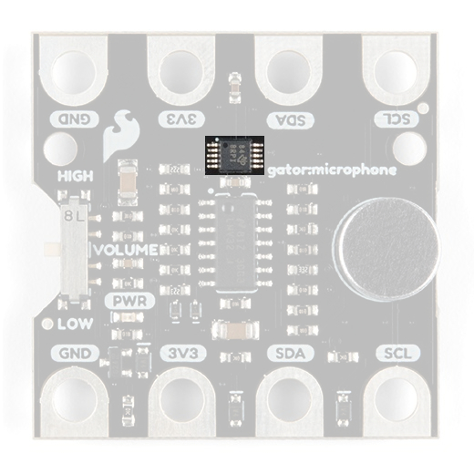
Hardware Overview
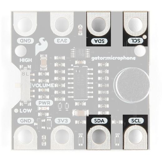
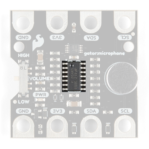
The gator:microphone consists of 4 pads for power and data. Additionally, there is a switch switch on the board to select different audio amplification levels; however, we will cover that in later.
| Contacts | Direction | Description |
|---|---|---|
| GND | N/A | Ground: Reference voltage and ground loop. |
| 3.3V | In | Power: Provides 3.3V to sensor. |
| SDA | Bi-directional | Data: Data and commands are transmitted between the sensor and microcontroller. |
| SCL | In | Clock: The microcontroller provides the timing needed to communicate on the data line. |
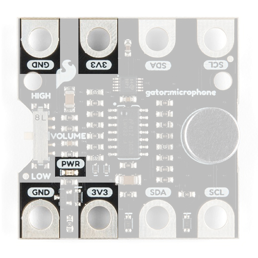
Power
The specified operating voltage for the VEML6070 is between 2.7V - 5.5V. For use with the gator:bit (v2) and micro:bit, you should provide 3.3V through the 3V3 and GND pads to keep the logic levels consistent.
Electret Microphone
An electret microphone is a capacitor based microphone similar to the ones found in phones or headsets. For the most part, users will only need to know that this is used to convert sound into an electrical signal (audio signal).
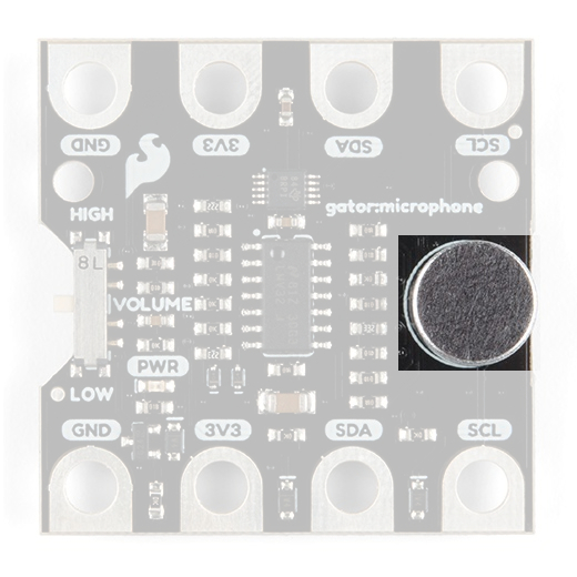
Here are some of the characteristics of the electret microphone from the datasheet:
| Characteristic | Range |
|---|---|
| Operating Voltage | 1.5V (Max 10V) |
| Supply Current | 0.3 mA (Max) |
| Directivity | Omnidirectional |
| Frequency Response | 20 to 16,000 Hz |
What is Sound?
Sound is pretty self explanatory if you can sense it. Physically, sound is most commonly described as a wave of pressure that propagates through a medium (solid, liquid, or gas... sound can't move through a vacuum). The field of science involving the generation, propagation and reception of these waves (and vibrations) is acoustics. There are many characteristics and factors to sound waves along with various applications and methods of manipulation.
Sound frequency and intensity range for the the threshold of human hearing. Click to enlarge. [Source: Elementary Physics I - PY105 Notes: Sound; Boston University]
A graph correlating sound intensity and perceived loudness. Click to enlarge. [Source: The Scientist and Engineer's Guide to Digital Signal Processing]
Humans perceive sound through their ears. The frequency range of human hearing is approximately 20 to 20,000 Hz. Humans can detect sound intensities from 10-12 W/m2 to 1 W/m2; scaled to 0 - 120 in decibels (dB)1. The human threshold for hearing or the smallest discernible sound we can detect, is around 0 phon on the equal-loudness contours (~20 µPa)2.
2. Source: The Scientist and Engineer's Guide to Digital Signal Processing↩
LMV324
The LMV324 is an operational amplifier (op-amp) configured to process the audio signals from the microphone. Op-amps are versatile and among the most widely used electronic components. For the most part, users will only need to know that the LMV324 is configured to provide for three different outputs: the amplified audio signal, the envelope of the audio signal, and a noise gate indicator.
Here are some of the characteristics of the LMV324 op-amp from the datasheet:
| Characteristic | Range |
|---|---|
| Operating Voltage | 2.7V to 5.5V |
| Supply Current | approx. 300 to 720 µA |
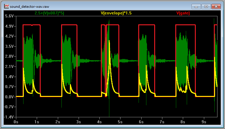
Below, is an signal capture of the three different outputs from the Sound Detector to illustrate their relation:
What is an Envelope Signal?
An envelope is a curve that essentially outlines the peaks or amplitude of a signal. There are various applications of an envelope in sound engineering. Most commonly this signal is used for preventing audio feedback, synthesizing a sound, or noise reduction in recordings. In the image below, an example of an envelope (yellow trace) of an audio signal as recorded from the Sound Detector, which is operates similarly to the gator:microphone.
Below are some additional resources on the applications of an envelope:
What is a Gate?
A gate is a comparative signal used to detect when the envelope signal passes a certain threshold. A common application is a noise gate, which is used to reduce the static noise of an recording by only passing music if a threshold is exceeded. Additionally, sound effects like the gated reverb, popularized in the 1980s, can also be created using special techniques.
Below are some additional resources on the applications for the gate:
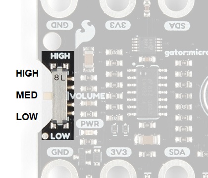
Selectable Gain Switch
This switch is used to select different gains value to amplify the audio signal from the microphone; high, medium, and low. For the most part, users will only need to know that high the higher the amplification (or gain), the more sensitive the gator:microphone will be to audio inputs.
| Switch Location | Resistor Value | Gain (Arithmetic) | Gain (Decibel) |
|---|---|---|---|
| High | 1 MΩ | 1000 | 60 dB |
| Medium | 100 kΩ | 100 | 40 dB |
| Low | 10 kΩ | 10 | 20 dB |
What is Gain?
Gain is the amplification of an electronic signal. In this instance, this is a voltage gain of the preamplifier from the original microphone electrical signal. In Low, the amplification is 10 times the original microphone voltage. In High, it is 1000 times the original microphone voltage or 100 times the voltage of the Low amplification.
Just like humans, sound can be too loud or soft for the electronics to discern any differences. When the electrical signal is too high, clipping can occur. To fix this the amplification should be lowered to bring the signal under the maximum range that can be measures. A signal is too soft, when the characteristics of the signal are below the resolution that you can measure. To fix this the amplification should be raised to detect those changes.
ADS1015
The ADS1015 is an analog to digital converter (ADC) used for converting analog voltages into a digital values that can be read by a microcontroller. The ADS1015 is used to measure the amplified audio signal, the envelope, and the gate. For the most part, users will only need to know I2C addresses to prevent address conflicts with other devices or sensors.
Here are some of the characteristics of the ADS1015 from the datasheet:
| Characteristic | Description |
|---|---|
| Operating Voltage (VDD) | 2.0V to 5.5V |
| Operating Temperature | -40°C to 125°C |
| Operation Modes | Single-Shot, Continuous-Conversion (Default), and Duty Cycling |
| Analog Inputs |
Measurement Type: Single-Ended (Default) or Differential Input Voltage Range: GND to VDD Full Scale Range (FSR): ±.256V to ±6.114V (Default: 2.048V) |
| Resolution |
12-bit (Differential) or 11-bit (Single-Ended) LSB size: 0.125mV - 3mV (Default: 1 mV) |
| Sample Rate | 128 Hz to 3.3 kHz (Default: 1600SPS) |
| Current Consumption (Typical) | 150μA to 200μA |
| I2C Address | 0x48 |
I2C Connection
I2C is a communication protocol used to transfer data between controller and peripheral devices. It is a 2-wire connection consisting of SDA (data) and SCL (clock). The protocol is pretty well defined so it can be shared with multiple devices. This is beneficial for daisy chaining multiple devices together on a single bus. The primary thing users will need to watch out for is address conflicts (you can't have devices with the same address).