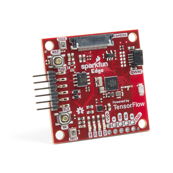
With the SparkFun Edge Development Board, edge computing is here! You've probably heard of this latest entry to the long lineage of tech buzzwords like "IoT," "LoRa," and "cloud" before it, but what is the edge and why does it matter? The cloud is impressively powerful but all-the-time connections require power and connectivity that may not be available. Edge computing handles discrete tasks such as determining if someone said 'start washer' and responding accordingly. The audio analysis is done at the "edge" rather than on the web. This dramatically reduces costs and complexity while limiting potential data privacy leaks.
So now that you've embarked upon the journey to the Edge, let's take a moment to get off on the right foot. In this hookup guide we will get familiar with the hardware available and how to connect to your computer, then we'll point you in the right direction to begin writing awesome applications using machine learning!
To follow along with this tutorial, you will need the following materials. You may not need everything though depending on what you have. Add it to your cart, read through the guide, and adjust the cart as necessary.
If you aren’t familiar with the following concepts, we recommend checking out these tutorials before continuing.
The Edge uses the Apollo3 Blue - the cutting-edge of high efficiency microcontrollers. This small BGA package packs quite a punch!

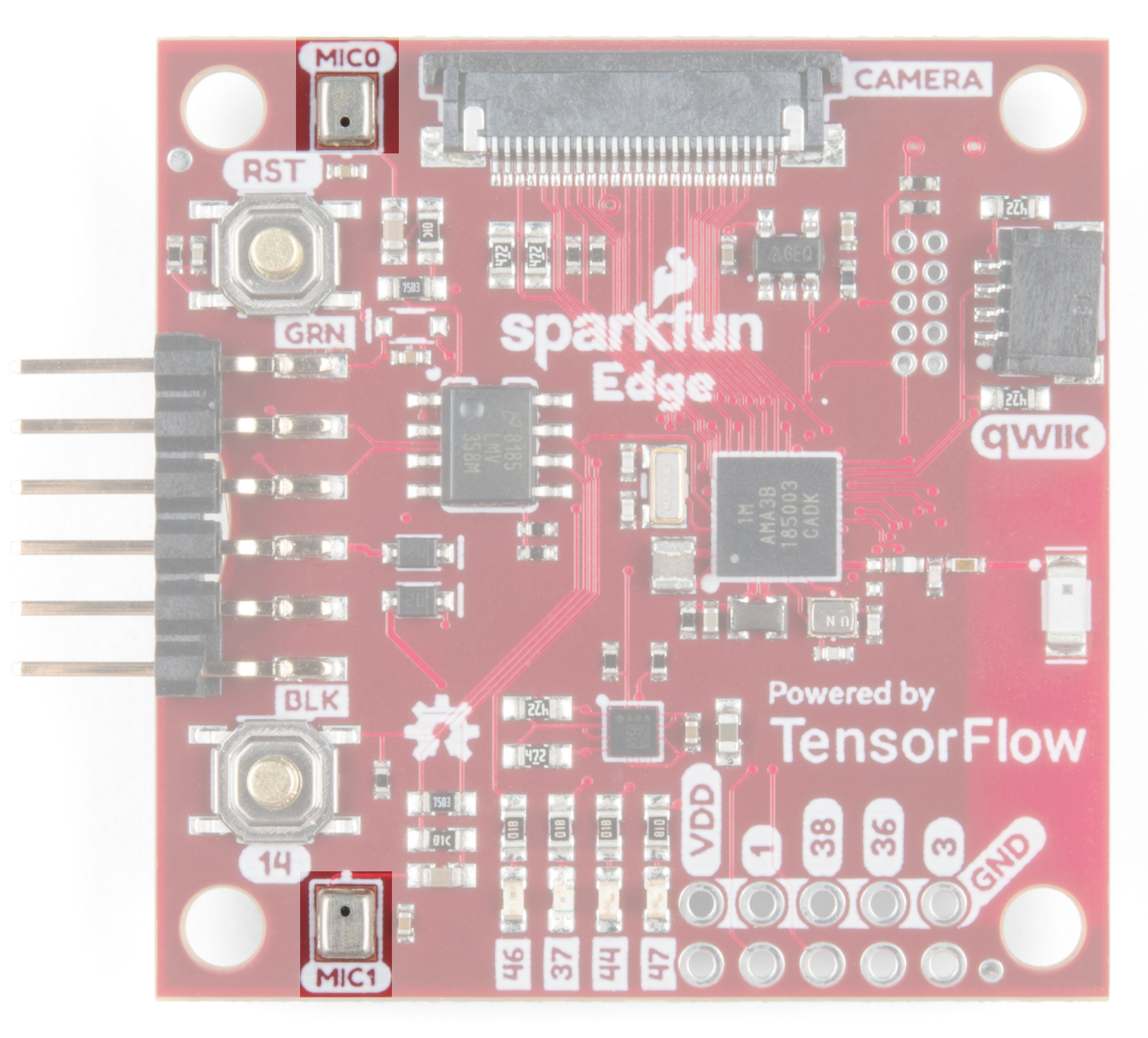
Such a formidable microcontroller would be wasted without a suite of cool sensors to use with it - that's why we've included two microphones, a 3-axis accelerometer, and a camera connector.
The Edge board contains Micro Electro-Mechanical microphones that are hooked up to an operational amplifier with 75x gain to make the best use of the Apollo3's built-in 14-bit analog to digital converter.
The Apollo3 microcontroller can use Direct Memory Access to take audio recordings without using processor cycles - that means you can process audio while you record the next sample!
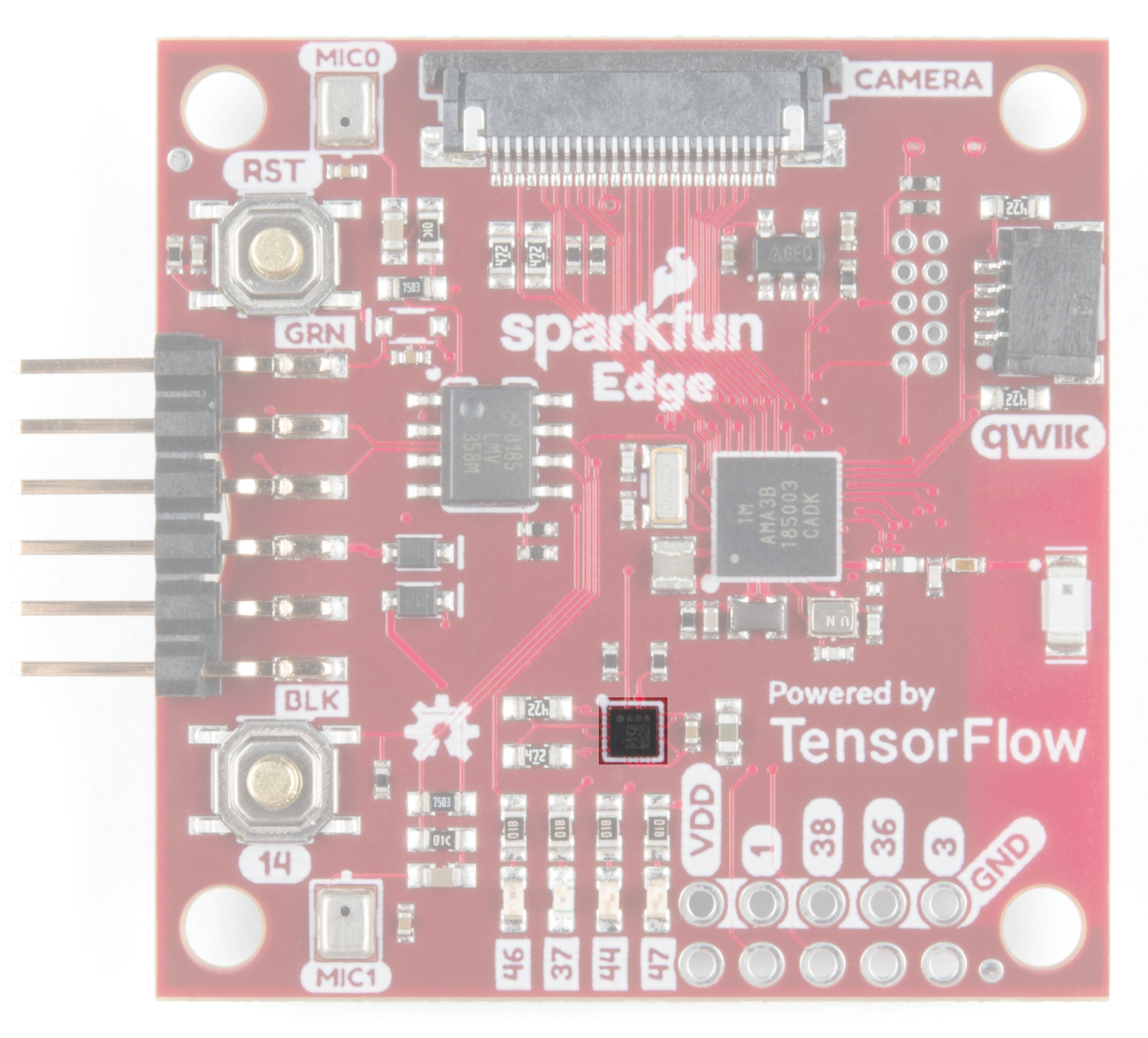
Dynamic interaction with the Edge is included right out of the gate with the onboard ST Microelectronics LIS2DH12 3-axis accelerometer. The accelerometer is on its very own dedicated I2C bus so there's no need to worry about address conflicts.
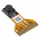
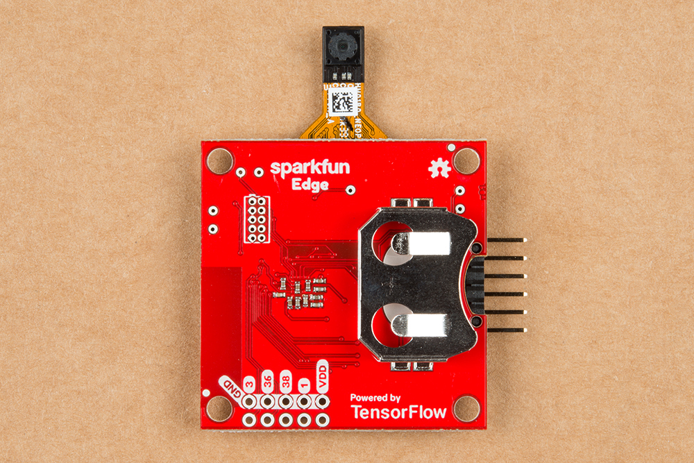
At the top of the board, we've included a camera connector to connect the Himax CMOS imaging camera.

If you need anything else to complete your application there are plenty of ways to connect to the Edge board. Among these are the FTDI UART header, a Qwiic connector, four GPIO pins, four LEDs, and last (but not least) a CR2032 coin cell holder.
You'll use this connector to program the Edge board, but after that you can also use it to talk to other systems that use a UART interface such as GPS or Serial LCD.

If you connect via UART, you'll likely use the CH340E driver. The driver should automatically install on most operating systems. However, there is a wide range of operating systems out there. You may need to install drivers the first time you connect the chip to your computer's USB port or when there are operating system updates. For more information, check out our How to Install CH340 Drivers Tutorial.
The Apollo3 can have up to 6 independent I2C ports. We've taken advantage of that fact by exposing a fresh I2C port through a Qwiic connector, allowing you to add a chain of I2C sensors without soldering.
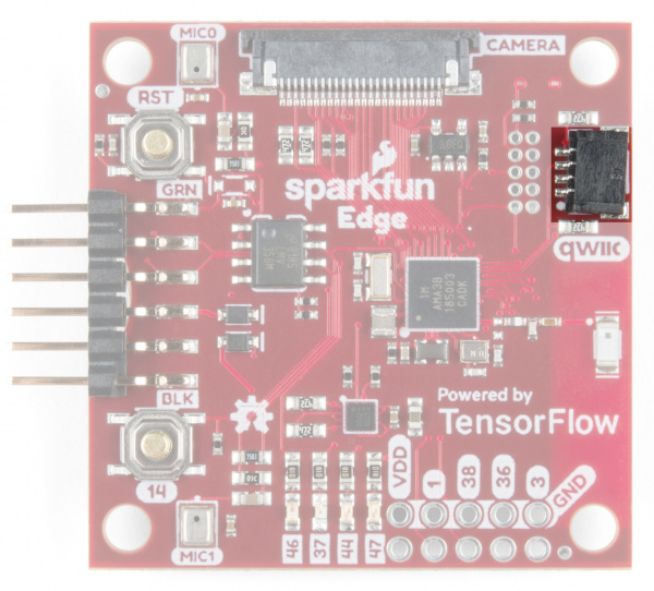
The Apollo3 comes with hardware support for a Bluetooth Low-Energy (BLE) radio. The Edge board pairs that up with a surface mount antenna. The BLE controller and host can be configured to support up to eight simultaneous connections -- security and extended packet length are also supported.
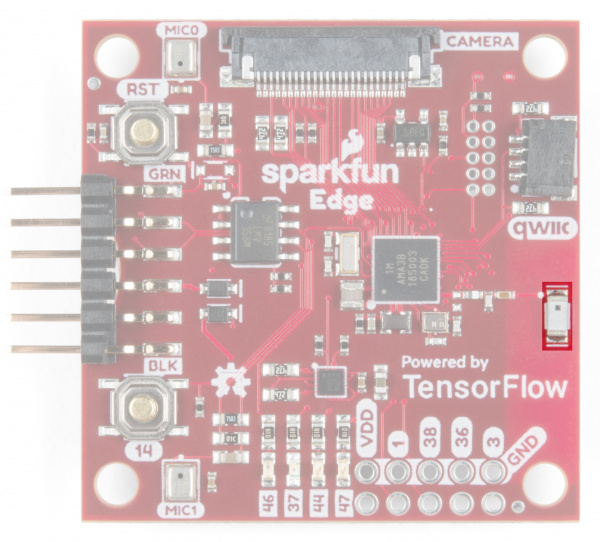
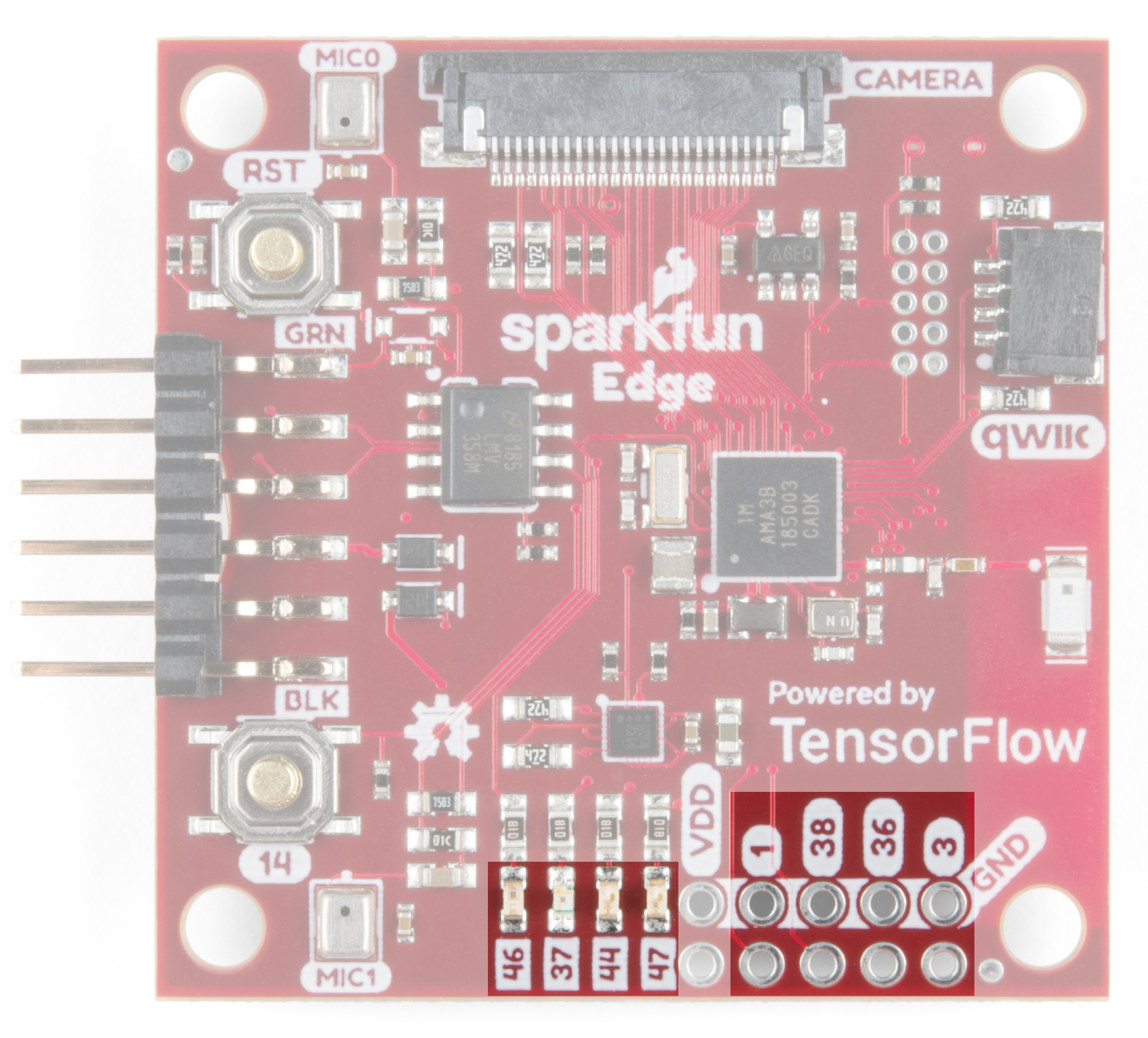
If all that wasn't enough there were still more pins available on the Apollo3, so we broke them out to four LEDs and four GPIO connections along the bottom edge. These are good for addition additional simple input or output capabilities to a project.
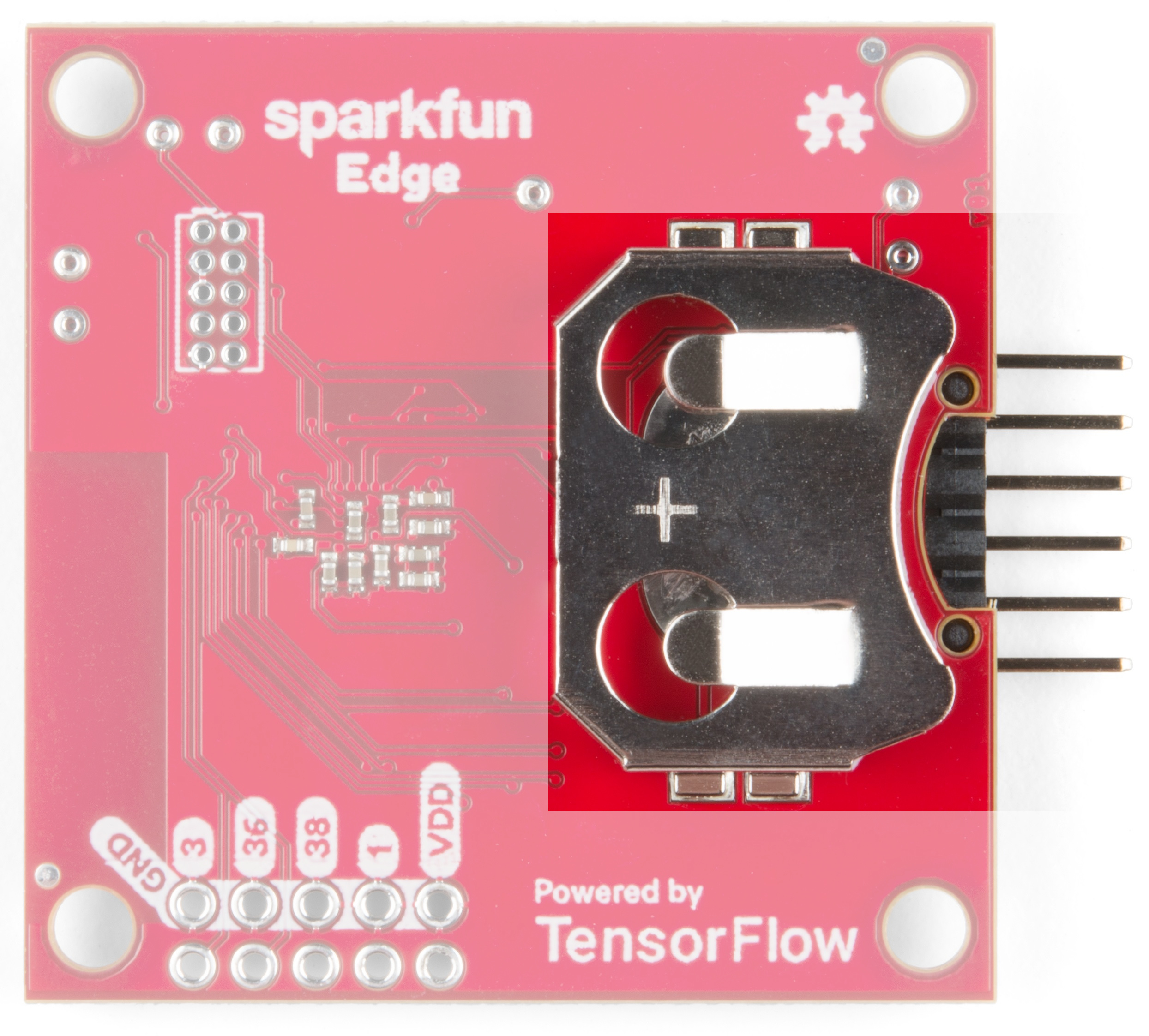
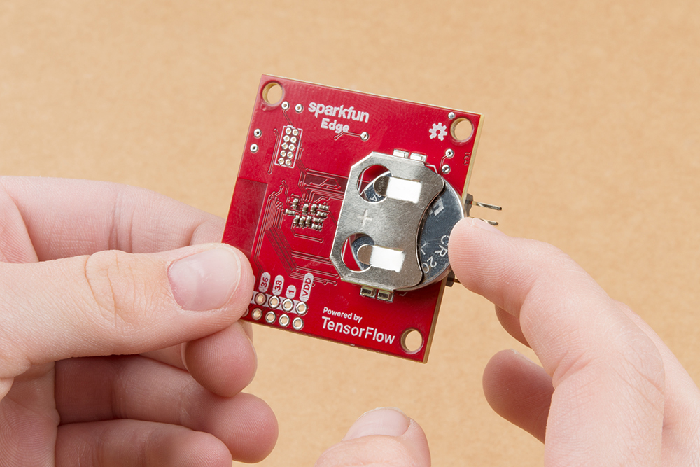
To demonstrate just how efficient this microcontroller is we included a coin cell battery holder on the bottom. That means that once your application is all ready you can take it to school on a key-chain and show it off to your best friend!
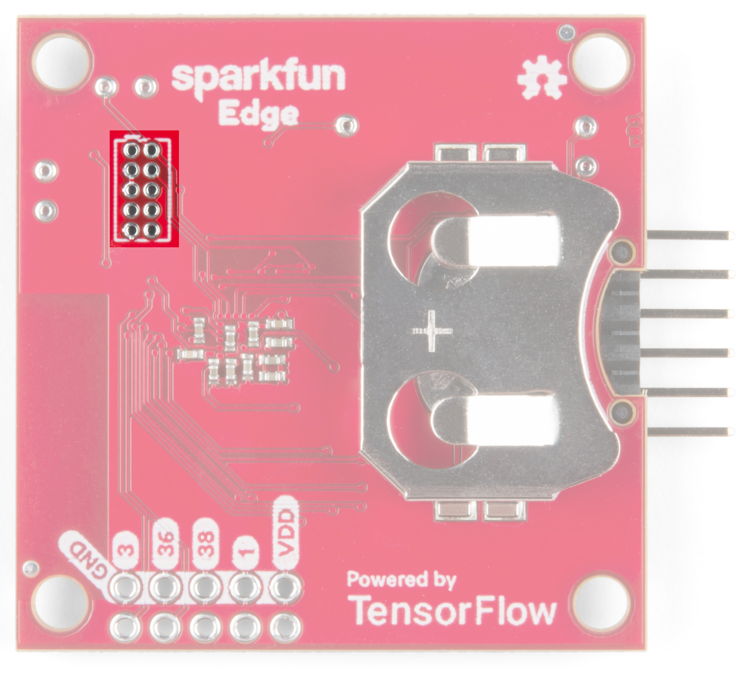
For anyone who wants the utmost performance out of the Edge board during the development process you can use the JTAG MIPI 10 standard 1.27mm pitch 2x5 connector to hook up your debugger/programmer.
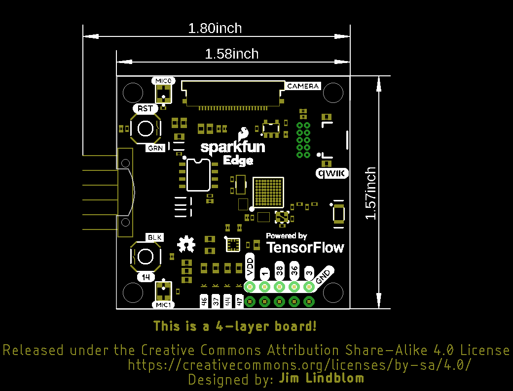
SparkFun Edge development board is measures 1.80"x1.57" and includes has four mounting holes
It's very easy to get started using the Edge board - all you need to do is provide power! Right off the bat you can try out the AI voice recognition by seeing the yellow LED light up for 'Yes' and the red LED light up for 'No.'
To power the board either place a charged CR2031 3V battery into the coin cell holder or plug in your USB-serial converter.
If you want to upload new code or see what the Edge board has to say to you then you'll need to be able to read the UART pins which are broken out just above the coin cell holder. The pinout is compatible with SparkFun serial breakouts like the Serial Basic Breakout or the new Serial Basic Breakout with USB C. The ability to toggle the DTR line from USB is required for bootloading.
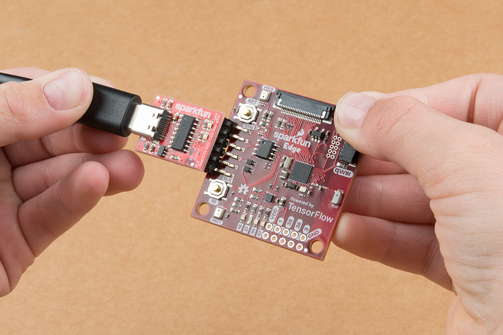
With your chosen method of connection at hand begin making the connections with care. If you have USB-serial bridge with the compatible pinout (order DTR, RXI, TXO, VCC, CTS, GND from the perspective of the bridge) you can simply make sure that the GRN and BLK labels match up between the bridge and the Edge board. If you are using some other way to view/send UART data then make sure to connect the TX of the bridge to the RX of the Edge and vice-versa. Also make sure to connect GND (closest to the BLK label on the Edge) and DTR (closest to the GRN label) pins. From the bridge's perspective RXI is next to DTR and TXO is next to RXI.
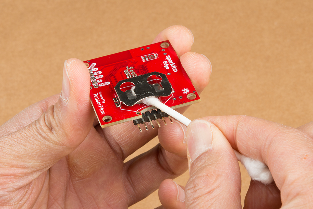
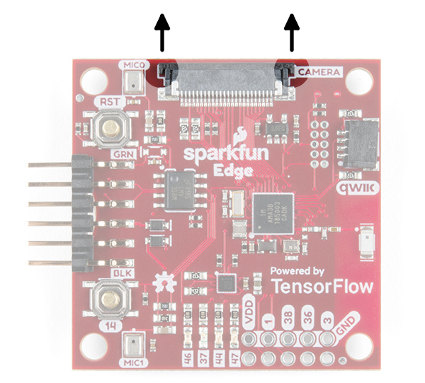
To connect the camera, you'll need to carefully slide the flexible ribbon cable connector's locking tab out. The locking tab slides out parallel to the board so you'll need to push each side of the tab with your fingernails. The image below highlights where you would need to place your fingernails to slide the tab out.
Once the locking tab is out, you can insert the camera connector into the slot. Face the camera's exposed contacts toward the PCB in order to make a connection with the connector's pins. Then insert the cable until it is firmly into the connector. Care must be taken to ensure that the ribbon cable does not have any sharp bends when installing the camera.

When ready, carefully slide the tab back into the locking position using your fingernails.

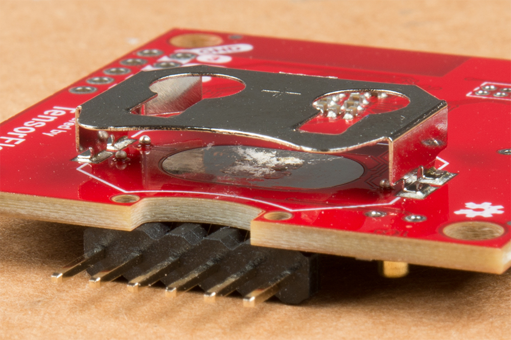
Your camera should look similar to the images below.
 |
 |
| Top View of Edge with Camera | Bottom View of Edge with Camera |
With the Edge boards you can add additional I2C sensors with the Qwiic connector and have access to four GPIO pins.
Connecting Qwiic sensors is as simple as chaining them together with Qwiic Cables and then linking that chain to the Edge board. Note, if you have many sensors (5 or more is a good rule of thumb) then you'll need to disconnect the I2C pullup resistors from a few of the boards.
The four available GPIO pins are pads 1, 3, 36, and 38 of the Apollo3. In addition to GPIO functionality some have additional special functions:
| Apollo3 Pad | Special Functions |
|---|---|
| 1 | UART0 TX |
| 3 | ADC Trigger1 |
| 36 | ADC Trigger1, UART1 RX, UART1 CTS, UART0 CTS, PDM Microphone DATA, 32 kHz Clock Output |
| 38 | ADC Trigger3, UART0 CTS, UART1 RX |
The Edge board takes advantage of the cutting-edge Apollo3 Blue microcontroller from Ambiq for incredibly high efficiency which allows AI applications to run on a coin cell power source. The cost of using the latest and greatest technology. In order to start developing your own applications you'll need to follow along with our extensive Ambiq Apollo3 Software Development Kit Setup Guide.
At the time of writing, support was only provided for the Ambiq Suite SDK. However, support is now included in the Arduino IDE. Check out the following for Programming the SparkFun Edge with Arduino!
Now that you are familiar with the hardware and setup, you should be able to start integrating the Edge Board into your projects. If you want more information on the Ambiq Apollo3 or the SparkFun Edge Board, check out some of the links below:
SparkFun Edge:
Working with the Apollo 3:
Need some inspiration for your next project? Check out some of these IoT tutorials!
Or check out this blog post for ideas.
learn.sparkfun.com | CC BY-SA 3.0 | SparkFun Electronics | Niwot, Colorado