SparkFun Absolute Digital Barometer - LPS28DFW (Qwiic) Hookup Guide
 El Duderino
 Introduction
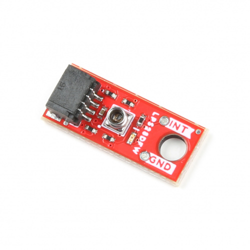
The SparkFun Absolute Digital Barometer - LPS28DFW (Qwiic) (Standard Size and Micro Size) offer a unique barometer breakout featuring the LPS28DFW from STMicroelectronics©. The LPS28DFW is an absolute barometer with a water-resistant package making it perfect for pressure measurement applications where the sensor is exposed to or even submerged in water1.
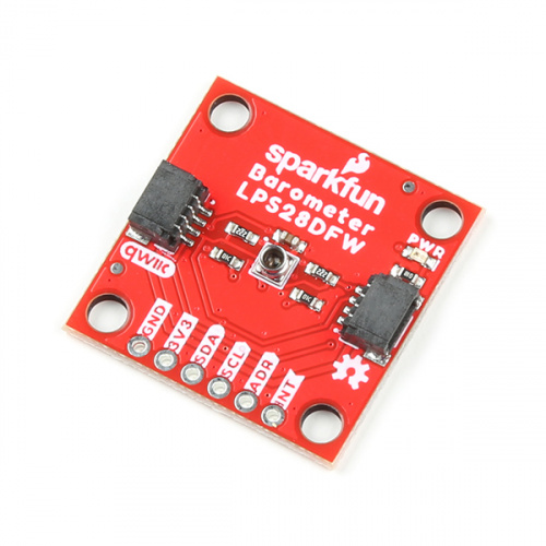
The sensor has two full-scale measurement ranges of 260 - 1260hPa and 260 - 4060hPa with an absolute pressure accuracy of 0.5hPa. The LPS28DFW is composed a piezoresistive pressure sensor with a metal lid and gel encasing to protect the sensing elements from water and other environmental hazards.
In this guide we'll cover the features and specifications of the LPS28DFW and other hardware present on these Qwiic breakouts as well as the Arduino library we have written to interact with the sensor.
Required Materials
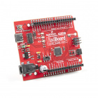
To follow along with this guide you will need a microcontroller to communicate with the LPS28DFW. Below are a few options that come Qwiic-enabled out of the box:

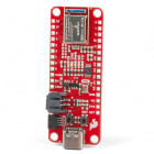

If your chosen microcontroller is not already Qwiic-enabled, you can add that functionality with one or more of the following items:


You will also need at least one Qwiic cable to connect the breakout to your microcontroller.


Suggested Reading
If you aren't familiar with the Qwiic system, we recommend reading here for an overview.
We would also recommend taking a look at the following tutorials if you aren't familiar with the concepts covered in them. If you are using one of the Qwiic Shields listed above, you may want to read through their respective Hookup Guides as well before you get started with the SparkFun Absolute Digital Barometer - LPS28DFW (Qwiic).
Serial Terminal Basics
Qwiic Shield for Arduino & Photon Hookup Guide
SparkFun Qwiic Shield for Arduino Nano Hookup Guide
Hardware Overview
In this section we'll take a closer look at the LPS28DFW and other hardware on these Qwiic breakouts.
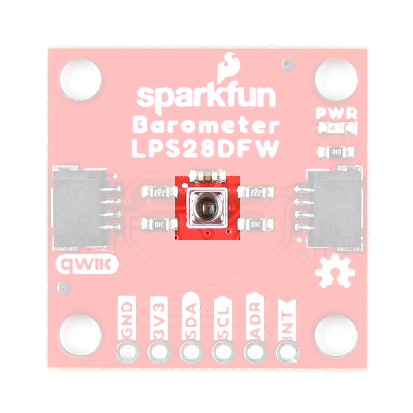
LPS28DFW Absolute Pressure Sensor
The LPS28DFW from STMicroelectronics is a digital output absolute pressure sensor with a gel-filled metal lid protecting the sensing element from moisture making it ideal for applications such as water depth measurements or other pressure-sensing projects in wet environments.
 |
 |
The LPS28DFW has two user-selectable measurement ranges (260 to 1260hPa and 260 to 4060hPa) with an absolute pressure accuracy of 0.5hPa and supports output data rates of 1 to 200Hz. The sensor supports communication over I2C and MIPI I3CSM interfaces (though I3C communication is not covered in this guide or the Arduino Library). The table below outlines some of the parameters for the LPS28DFW. For a complete overview of the sensor, refer to the datasheet.
| Parameter | Min. | Typ. | Max. | Units | Notes |
|---|---|---|---|---|---|
| Supply Voltage | 1.7 | - | 3.6 | V | Breakouts run the sensor at 3.3V |
| Supply Current | - | 1.7 | - | µA | Average Selection (AVG)=4 and Output Data Rate (ODR)=1Hz. |
| - | 9.4 | - | AVG=128 and ODR=1Hz. | ||
| - | 0.9 | - | Sensor in power-down mode. | ||
| Operating Temperature Range | -40 | - | +85 | °C | |
| Operating Pressure Range | |||||
| Mode 1 | 260 | - | 1260 | hPa | |
| Mode 2 | 260 | - | 4060 | ||
| Pressure Sensitivity | |||||
| Mode 1 | - | 4096 | - | LSB/hPa | |
| Mode 2 | - | 2048 | - | ||
| Relative Pressure Accuracy | Test Conditions: | ||||
| Mode 1 | - | ±0.015 | - | hPa | Temp. = 25°C Press.=800~1100hPa |
| Mode 2 | - | ±1 | - | Temp. = 25°C Press. = 2060~4060hPa | |
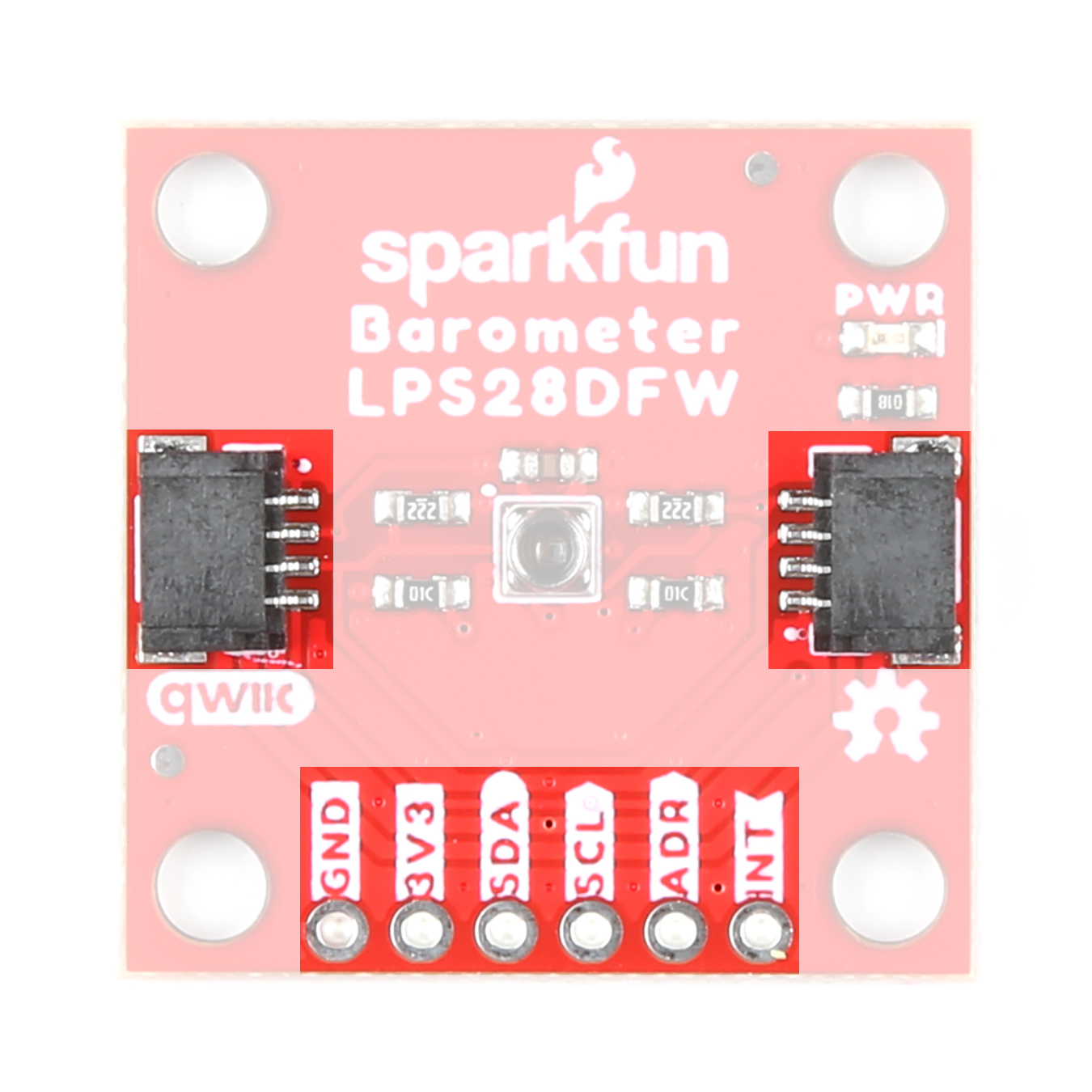
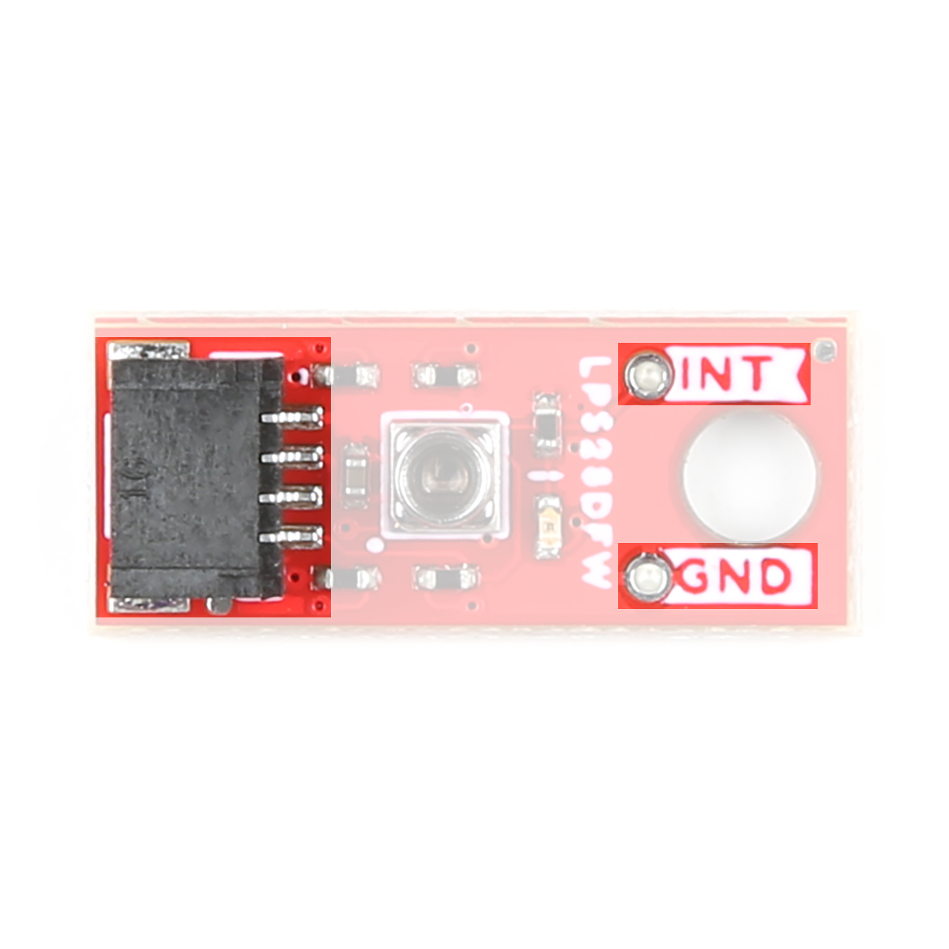
I2C Interface
The standard size routes the I2C interface to a pair of Qwiic connectors as well as a 0.1"-spaced PTH header for users who prefer a traditional soldered connection. Both breakouts route the sensor's interrupt (INT) pin to a PTH pin.
 |
 |
Both boards set the LPS28DFW's I2C address to 0x5C by default. Adjust the ADR jumper to change to the alternate address (0x5D) or open it completely to toggle the address using the ADR PTH pin (Standard size only). More information on this jumper in the Solder Jumpers section below.
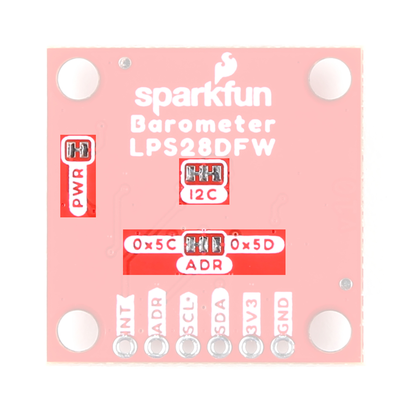
Solder Jumpers
Both LPS28DFW Qwiic breakouts have three solder jumpers labeled: PWR, I2C, and ADR. The table below outlines the jumpers' label, default state, function, and any notes about their behavior.
 |
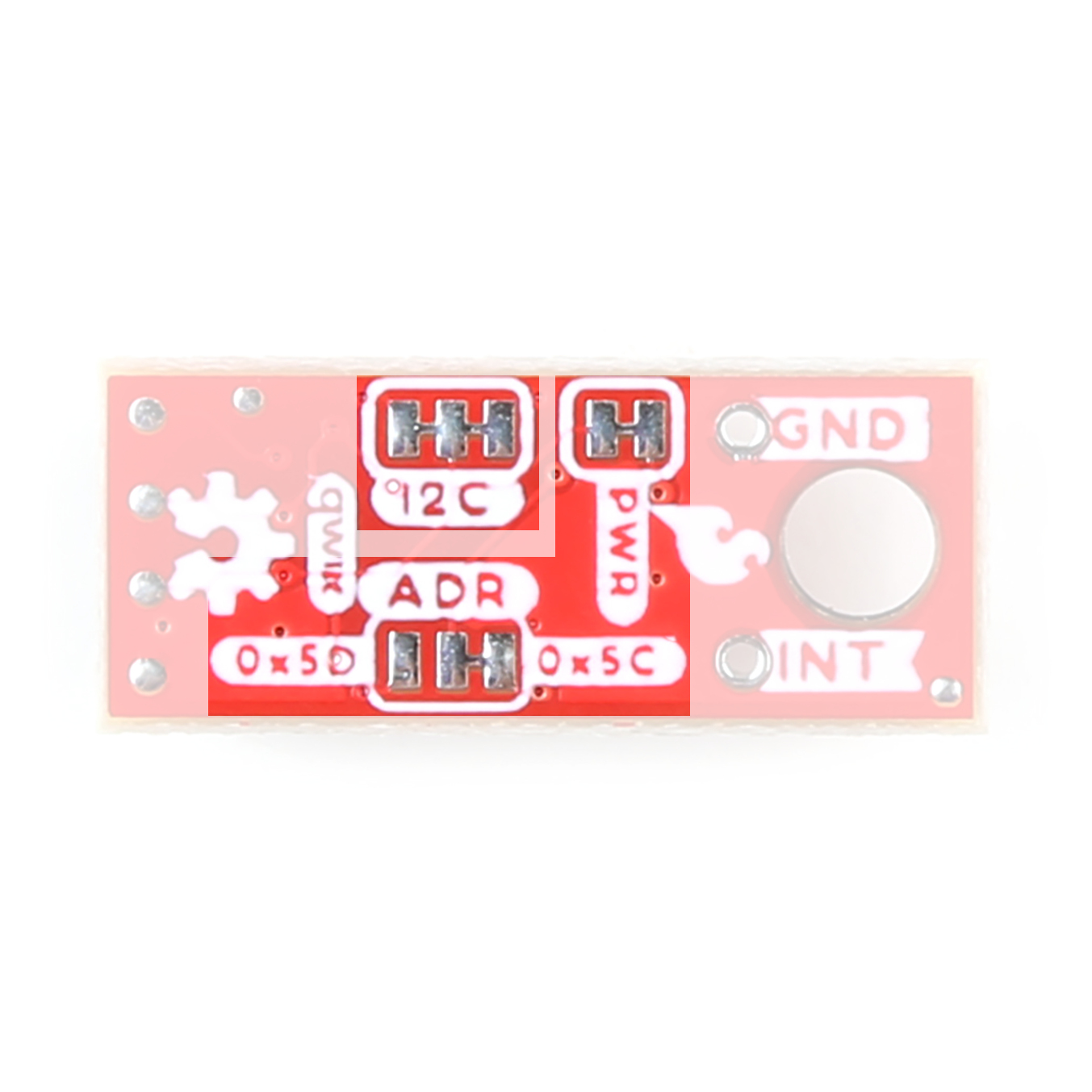 |
| Label | Default State | Function | Notes |
|---|---|---|---|
| PWR | CLOSED | Completes the Power LED circuit. | Open to disable the Power LED. |
| I2C | CLOSED | Pulls the SDA/SCL lines to VCC (3.3V) through a pair of 10kΩ resistors. | Open to disable pull-up resistors on the I2C lines. |
| ADR | SEE NOTE | Sets the I2C address of the LPS28DFW. | I2C address is 0x5C by default. Sever the trace connecting the center pad to the pad labeled 0x5C and connect it to the pad labeled 0x5D to change the address. |
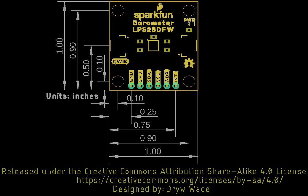
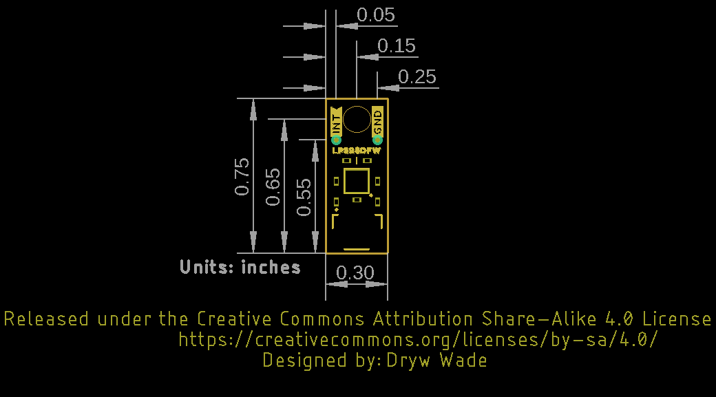
Board Dimensions
The boards match the Standard and Micro form-factors for Qwiic breakouts measuring 1" x 1" (Standard) and 0.5" x 0.3" (Micro). The Standard breakout has four mounting holes and the Micro has one. All mounting holes fit a size 4-40 screw.
 |
 |
Hardware Assembly
Now that we're familiar with the LPS28DFW breakouts, we can start assembling our circuit.
Qwiic/I2C Assembly
The fastest and easiest way to get started using the breakouts is to connect the Qwiic connector on the breakout to a Qwiic-enabled development board like the SparkFun RedBoard Artemis with a Qwiic cable and as shown in the image below.
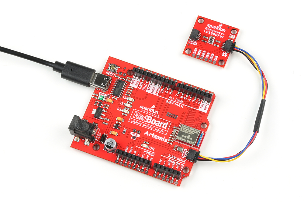
If you would prefer a more secure and permanent connection with the Standard Size breakout, you can solder headers or wire to the PTH header on the board.
Conformal Coating for Waterproofing
While the LPS28DFW's gel filled cap protects the sensing element from liquid and other environmental effects, the breakouts do not have any coating to protect the other components from damage due to exposure to liquids. A protective coating is required for applications that expose the board(s) to liquid. This tutorial on customizing LilyPad LED colors has tips on how to apply a conformal coating.
LPS28DFW Arduino Library
Note: This library assumes you are using the latest version of the Arduino IDE on your desktop. If this is your first time using Arduino, please review our tutorial on installing the Arduino IDE. If you have not previously installed an Arduino library, please check out our installation guide.
The SparkFun LPS28DFW Arduino Library provides a quick and easy way to get started configuring and measuring pressure data from the sensor. Install the library using the Arduino Library Manager tool by searching for "SparkFun LPS28DFW". Users who prefer to manually install the library can download a copy of it from the GitHub repository by clicking the button below:
Library Functions
The list below outlines and describes the functions available in the SparkFun LPS28DFW Arduino Library. For detailed information on the parameters and use of all functions, refer to the .cpp file in the library.
Device Initialization and Configuration
- 'int32_t begin(uint8_t address = LPS28DFW_I2C_ADDRESS_DEFAULT, TwoWire& wirePort = Wire);' - Begin communication with the sensor over I2 at the defined address and on the defined port. If no error occur, perform a soft reset and initialize the sensor.
- 'int32_t init();' - Enables the BDU and IF_ADD_INC bits in the control registers.
- 'int32_t boot();' - Enables the BOOT bit in the control registers
- 'int32_t reset();' - Resets the sensor.
- 'int32_t setModeConfig(lps28dfw_md_t* mode);' - Configures the operation mode settings for the sensor including range and ODR.
- 'int32_t getModeConfig(lps28dfw_md_t* mode);' - Returns the operation mode settings.
- 'int32_t getStatus(lps28dfw_stat_t* status);' - Returns the sensor status bits such as data ready, overrun, etc.
Sensor Data
- 'int32_t getSensorData();' - Get pressure data from the sensor.
Interrupt Control and Feature Selection
- 'int32_t setInterruptMode(lps28dfw_int_mode_t* intMode);' - Configures the interrupt pin to be either HIGH/LOW and LATCHED/PULSED.
- 'int32_t enableInterrupts(lps28dfw_pin_int_route_t* intRoute);' - Enables the data ready and FIFO interrupt conditions.
- 'int32_t getInterruptStatus(lps28dfw_all_sources_t* status);' - Returns the status of the interrupt flags.
FIFO Buffer Control
- 'int32_t setFIFOConfig(lps28dfw_fifo_md_t* fifoConfig);' - Sets the FIFO configuration parameters.
- 'int32_t getFIFOConfig(lps28dfw_fifo_md_t* fifoConfig);' - Returns settigs of FIFO buffer.
- 'int32_t getFIFOLength(uint8_t* numData);' - Returns the number of samples stored in the FIFO buffer (up to 128).
- 'int32_t getFIFOData(lps28dfw_fifo_data_t* data, uint8_t numData);' - Gets pressure data from the FIFO buffer.
- 'int32_t flushFIFO();' - Clear all data from the FIFO buffer.
Reference Mode Control
- 'int32_t setReferenceMode(lps28dfw_ref_md_t* mode);' - Sets the sensor to operate in reference mode. When called it stores the latest pressure data as a reference pressure. The reference pressure can be used with Threshold Mode to trigger interrupts.
- 'int32_t setThresholdMode(lps28dfw_int_th_md_t* mode);' - Configures the sensor to trigger interrupts when the pressure measured exceeds a threshold relative to the defined reference pressure.
- 'int32_t getReferencePressure(int16_t* pressRaw);' - Returns the value stored for the reference pressure.
Arduino Examples
Now let's take a closer look at a few of the examples included in the LPS28DFW Arduino Library.
Example 1 - Basic Readings
The first example covers the basics of polling the LPS28DFW for pressure and temperature data over I2C. Open the example by navigating to File > Examples > SparkFun LPS28DFW Arduino Library > Example1_BasicReadings. Select your Board and Port and click the Upload button. Once upload completes, open the serial monitor with the baud set to 115200 and watch pressure and temperature data print out.
The code assumes the sensor uses the default I2C address so if you have adjusted the ADR jumper to switch to the alternate address, comment/uncomment the line with the correct value listed:
language:c
uint8_t i2cAddress = LPS28DFW_I2C_ADDRESS_DEFAULT; // 0x5C
//uint8_t i2cAddress = LPS28DFW_I2C_ADDRESS_SECONDARY; // 0x5D
The example attempts to initialize the sensor with default settings in I2C at the specified address. If it cannot initialize properly, the code prints out an error in over serial:
language:c
while(pressureSensor.begin(i2cAddress) != LPS28DFW_OK)
    {
        // Not connected, inform user
        Serial.println("Error: LPS28DFW not connected, check wiring and I2C address!");

        // Wait a bit to see if connection is established
        delay(1000);
    }
If you see this error, double check the sensor is connected properly and set to the correct I2C address and reset the development board or re-upload the code.
The main loop gets temperature and pressure data measurements from the sensor every second:
language:c
{
    // Get measurements from the sensor. This must be called before accessing
    // the pressure data, otherwise it will never update
    pressureSensor.getSensorData();

    // Print temperature and pressure
    Serial.print("Temperature (C): ");
    Serial.print(pressureSensor.data.heat.deg_c);
    Serial.print("\t\t");
    Serial.print("Pressure (hPa): ");
    Serial.println(pressureSensor.data.pressure.hpa);

    // Only print every second
    delay(1000);
}
Try moving the sensor up and down to see the pressure data change.
Example 3 - Interrupts
Example 3 shows how to set up and use data ready interrupts triggered by the sensor. The code defaults to use D2 as the interrupt pin on a connected development board. If your board does not support external interrupts on D2, adjust this line:
language:c
int interruptPin = 2
If you're not sure which pins on your development board support external interrupts, this reference page lists usable digital pins for most common Arduino development boards.
After initializing the LPS28DFW, the code sets the ODR to 1Hz, configures the interrupt pin to operate in Data Ready mode and attaches the interrupt to the pin defined above (D2:
language:c
ps28dfw_md_t modeConfig =
    {
        .fs  = LPS28DFW_1260hPa,    // Full scale range
        .odr = LPS28DFW_1Hz,        // Output data rate
        .avg = LPS28DFW_4_AVG,      // Average filter
        .lpf = LPS28DFW_LPF_DISABLE // Low-pass filter
    };
    pressureSensor.setModeConfig(&modeConfig);

    // Configure the LPS28DFW interrupt pin mode
    lps28dfw_int_mode_t intMode =
    {
        .int_latched  = 0, // Latching mode (not including data ready condition)
        .active_low   = 1, // Signal polarity
        .drdy_latched = 0  // Latching mode (data ready condition only)
    };
    pressureSensor.setInterruptMode(&intMode);

    // Configure the LPS28DFW to trigger interrupts when measurements finish
    lps28dfw_pin_int_route_t intRoute =
    {
        .drdy_pres = 1, // Trigger interrupts when measurements finish
        .fifo_th   = 0, // Trigger interrupts when FIFO threshold is reached
        .fifo_ovr  = 0, // Trigger interrupts when FIFO overrun occurs
        .fifo_full = 0  // Trigger interrupts when FIFO is full
    };
    pressureSensor.enableInterrupts(&intRoute);

    // Setup interrupt handler
    attachInterrupt(digitalPinToInterrupt(interruptPin), lps28dfwInterruptHandler, RISING);
}
The main loop waits for a Data Ready interrupt event to occur and then prints out the data from the sensor over serial.
Example 5 - Reference Mode
Example 5 demonstrates how to set and use reference measurements to trigger interrupts from the LPS28DFW. Reference mode allows you to store a pressure value as a reference and then monitor the sensor's output to trigger an interrupt if it goes above or below the threshold value by a specified amount.
The reference value register is READ only so we cannot manually set the threshold value in the code. Instead, the code waits for the user to input they are ready to set the threshold value and then enter any key to trigger the event.
The code sets the over and under pressure thresholds to 1hPa above/below the stored reference pressure. If you want to adjust it, change the settings here:
language:c
lps28dfw_int_th_md_t thresholdMode =
    {
        .threshold = 16, // Threshold above/below the reference pressure (eg. 16 = 1hPa in 1260hPa range)
        .over_th = true, // Enable the "over pressure" interrupt condition
        .under_th = true // Enable the "under pressure" interrupt condition
    };
    pressureSensor.setThresholdMode(&thresholdMode);
Note, the threshold value must be set in multiples of 16 when in Mode 1 (260-1260hPa) and multiples of 8 when in Mode 2 (260-4060hPa). For example, to set the pressure threshold to above/below 1hPa, set the .threshold to 16.
After uploading, open the serial monitor with the baud set to 115200 and get the sensor ready to take the threshold measurement. Wait for the prompt and press any key to set the value. If successful, you should see the serial printout below:

Once the threshold is set, the main loop prints out temperature and pressure data and waits for an interrupt event to trigger if the pressure readings go above or below the threshold pressure by 1hPa.
Troubleshooting
Waterproofing the Breakouts
As mentioned previously, these breakouts do not have any coating on them to protect the components from water damage so users who intend to take advantage of the LPS28DFW's water resistant design will need to coat the breakout in a waterproof coating such as conformal coating. This tutorial on customizing LilyPad LED colors has tips on how to apply a conformal coating.
Pressure Data as Altitude
If you want to use the pressure data from the LSP28DFW to determine the altitude of the sensor, refer to this section of our MPL3115A2 Breakout Hookup Guide for more information on how to manipulate and correctly interpret pressure data.
General Troubleshooting
If you need technical assistance and more information on a product that is not working as you expected, we recommend heading on over to the SparkFun Technical Assistance page for some initial troubleshooting.
If you don't find what you need there, the SparkFun Forums are a great place to find and ask for help. If this is your first visit, you'll need to create a Forum Account to search product forums and post questions.
Resources and Going Further
That's a wrap for this hookup guide. At this point you should have your breakout up and running returning pressure data over I2C. Check out the resources below for more information on the breakouts and the LPS28DFW:
- Schematics
- Eagle Files
- Board Dimensions
- Datasheet (LPS28DFW)
- Qwiic Info Page
- LPS28DFW Arduino Library
- Hardware GitHub Repo