Soil moisture-sensing by hacking a solar light
 Sarah Al-Mutlaq
Introduction
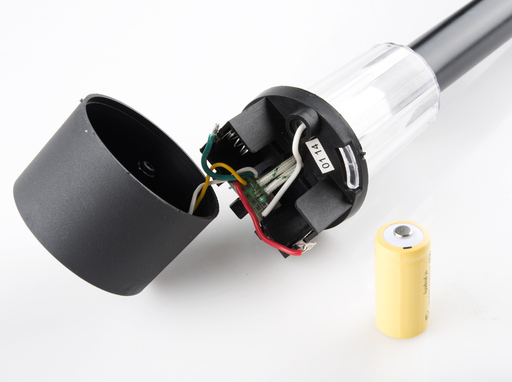
In this tutorial, we are going to take a simple solar powered pathway light from a department store and rewire it to be a soil moisture sensor. The finished design will turn on an LED when the soil dries up.
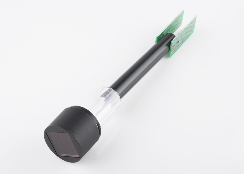
For this tutorial, I purchased a $2 solar pathway light from McGuckins Hardware, but most any standard solar pathway light should do the trick. As far as the circuitry goes, most path lights use a very specialized chip, for which a datasheet can be difficult to find. The chip in my path light was an XY8018 which was set up with an inductor, the solar panel, an LED and a Nickel-Cadmium rechargeable battery. It seems others have had the same issue identifying the IC. While it's always wise to know what you're working with, this project is easy to accomplish without that information.
Materials Used:
Tools Used:
- Wire
- Soldering Iron
- Solder
- Hot glue gun
Other Materials You Could Use:
- Galvanized nails
- Steel rods
- Copper tape
- Gypsum plaster
Suggested Reading
Circuitry
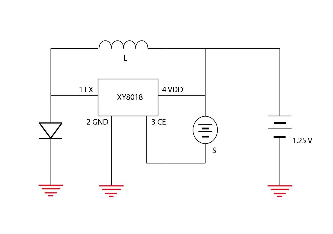
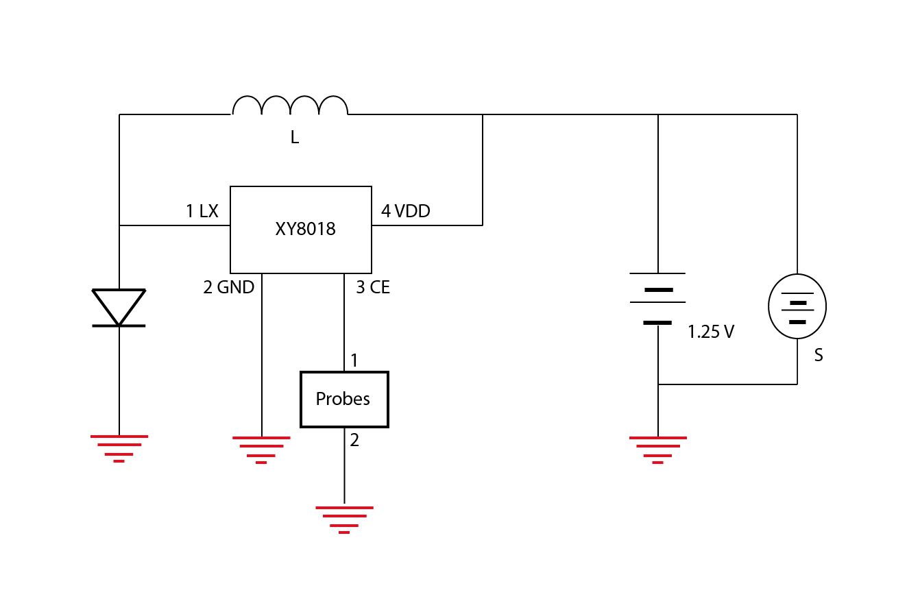
The pathway light chip (the XY8018 here), in its original circuit is meant to turn on an LED when the solar panel is not receiving light, acting like a short circuit (or “high”), and turn off the LED and have the solar panel charge the battery when the solar panel is receiving light (or “low”). Using this information about how the chip functions we can rewire our probes to the chip to be the dictating factor to whether the LED is on or not.
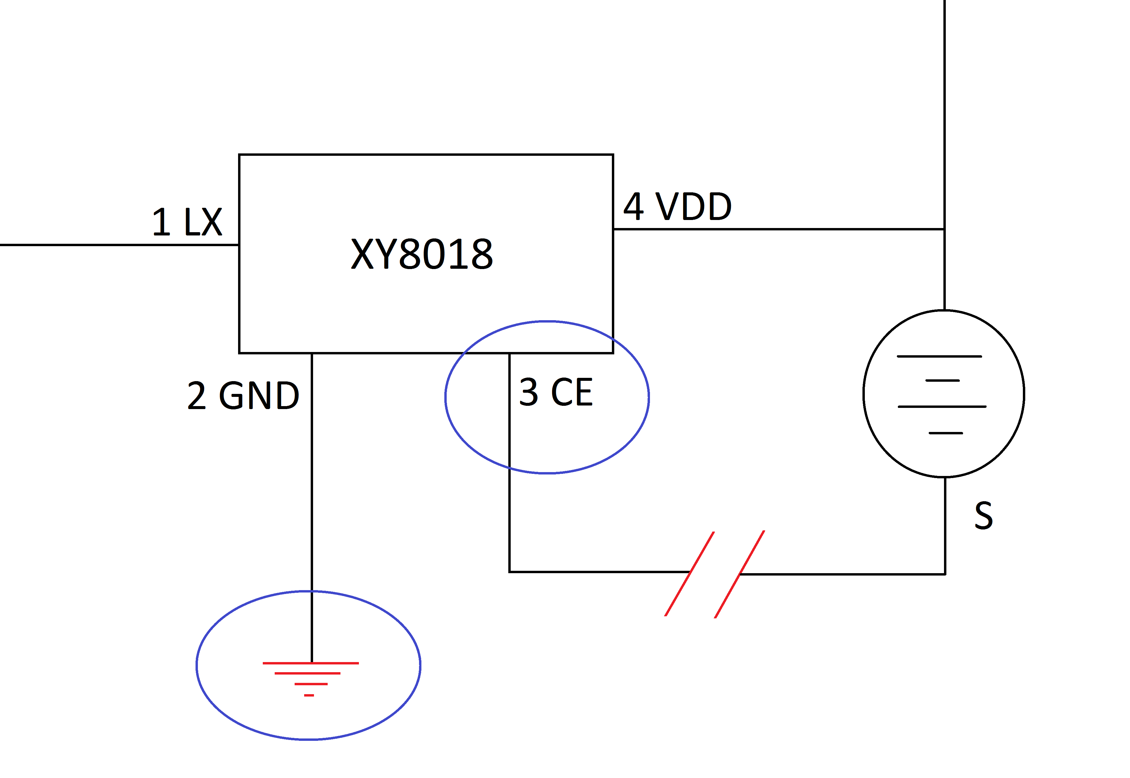
To set up a circuit that will turn the LED on when the soil is dry, we can wire one probe to pin 3 of the chip, where the solar panel was hooked up, and the other to ground, which will allow the LED to turn on when there is a high resistance between ground and pin 3 (when there is less water between the probes). The LED will turn off when there is more water between the probes and the resistance decreases between pin 3 and ground, pulling it low.
Probes
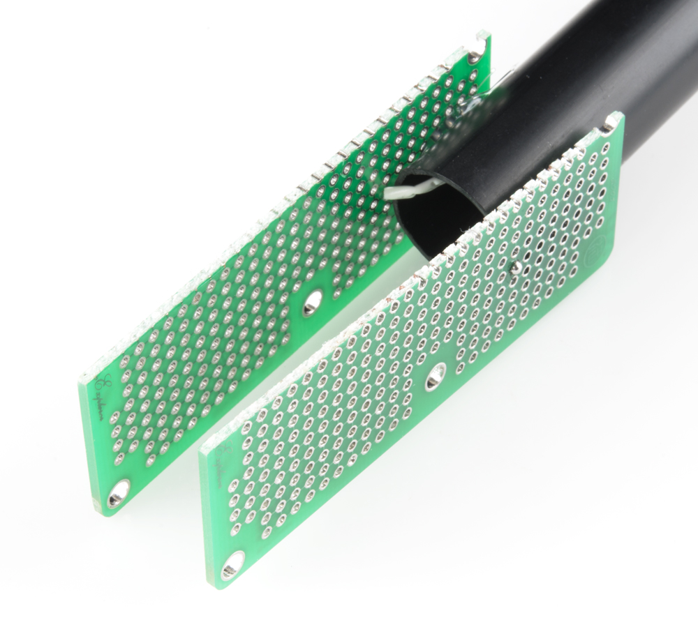
For my probes, I choose to use a small perf board, with all of its holes routed together, on both sides. I chose it because it was what I had laying around and it had a large conducting surface area. I cut it in half to make the two probes. The two halves where then hot glued to the end of the pathway light. Last, wires where piped through the shaft to be soldered to the probes from the main circuit.
The probes could be made of many other things as well. Galvanized nails, a PCB board with copper tape on them, two steel rods, and other like things would also work fine as probes. Some things you should consider when choosing your probes is how moist your soil will be and if corrosion is going to become a large factor. If so, you might want to go with a metal that is less likely to corrode, such as galvanized steel. Also, you can encase your probes in a gypsum plaster to help prevent corrosion and keep your probes at a set distance.
Rewiring
The good news is that this IC works as is, even with our modification, so it requires no reprogramming whatsoever. That is also the bad news, since you cannot change the threshold at which the LED will illuminate. To change the threshold, you can move your probes closer together or further away. The closer they are, they better they will be at sensing small amounts of water, so the LED will only turn on when the soil is very very dry. The further apart the probes are, the more water that is needed to turn off the LED. Play around with your soil type, and what levels you would like your LED to turn on and off, and decide from there the spacing and possibly what type of probe you would like to use.
The only other thing I wanted this circuit to do was to always have the solar panel charging the battery. To accomplish that, wire the solar panel in parallel with the battery by soldering the solar panel wire that was attached to pin 3 to the ground side of the battery. This makes the final circuit look like this:
Usually for a more complex circuit, or a different battery such as a Lithum-ion battery, you would not want to hook up the power source directly to charge the battery like this, since overcharging is an issue. Here that issue is small, and even if the battery was overcharge it shouldn't explode or anything, just decrease the lifetime of the battery. So it's not very good practice to wire the solar panel to the battery like this, but for our purposes here it works.
Putting it all together
I kept the same PCB found in the pathway light and rewired the solar panel directly to the board. I added some wires straight from the PCB to lead down to my circuit board probes that I hot glued to the pathway light stand. This worked for me, but you could certainly use a new board in the pathway light to make soldering the parts together easier, though space is a constraint.
There are many other things you could add to this simple circuit if you like. The main constraint is due to the fact that it's running off of a solar panel and battery, and it can not produce a whole lot of current. Keep that in mind if you decide to build your own version.
Resources and Going Further
There are countless solar pathway lights and a number of ways to hack them. We'd love to see what kind of solar hacks you can come up with.
Want more fun in the sun? Check out these other SparkFun products and tutorials.
- The Botanicalls Kit allows your plants to tweet you when they're getting too dry.
- The Sunny Buddy Hookup Guide will teach you how to incorporate solar charging and power into your next electronics project.
- Add soil moisture readings to your weather station using what you learned in this tutorial.