Now that you've successfully made a Simon Says board and thoroughly impressed all your friends at home, it's time to learn how to change your Simon Says board into your own unique project!! That's right, your Simon Says board is capable of doing MUCH more than playing the Simon Says game. It can be re-programmed to do whatever you like. In this tutorial we will:
For the fourth part of the tutorial, we will show you how you can use your Simon Says board to detect light. This example will require a photocell, a 10K resistor and a soldering iron. However, you can still upload the example code and listen to disco mode (without soldering on the light sensor).
In this tutorial, we will show you how to re-program your Simon Says board. We will guide you through setting up the software and hardware. To do this, you will need a PC or Mac. Assuming that you have one of the Simon Says boards soldered, we will require an additional three pieces of hardware to upload code to the microcontroller:
The following is a recommended list of materials you'll need to modify the board.
If you aren’t familiar with the following concepts, we recommend checking out these tutorials before continuing.
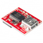
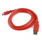
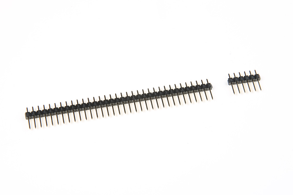
To upload new code to the board, we need a mini-B USB Cable, FTDI basic Breakout, and a 1x6 row from a row of straight male headers.
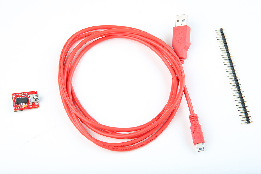
If you bought a 40-pin strip of breakaway male headers from the website, you will have to break off a 6-pin section from the larger strip. You can cut these using some pliers, or snap them using your hands by bending the strip at the desired break-point.
These 3 items will be the link between your Simon Says board and your computer. First, plug in the 6-pin male header into your FTDI basic board. Make sure to put the longer end of the headers into the FTDI like so:
|
|

|
Next, plug in the USB cable into your computer. Then plug the other end into your FTDI basic board. You should notice that the RX and TX leds on the FTDI blink a few times. This indicates that your FTDI is communicating with your computer.
|
|
|
Now you are ready to link your computer to your Simon Says board. First you must find the programming port on your Simon Says board. You will find it near one of the edges of the Simon Says board. It looks like 6x holes with nothing soldered into them. Below shows images of the FTDI header for the PTH and SMD versions.

|

|
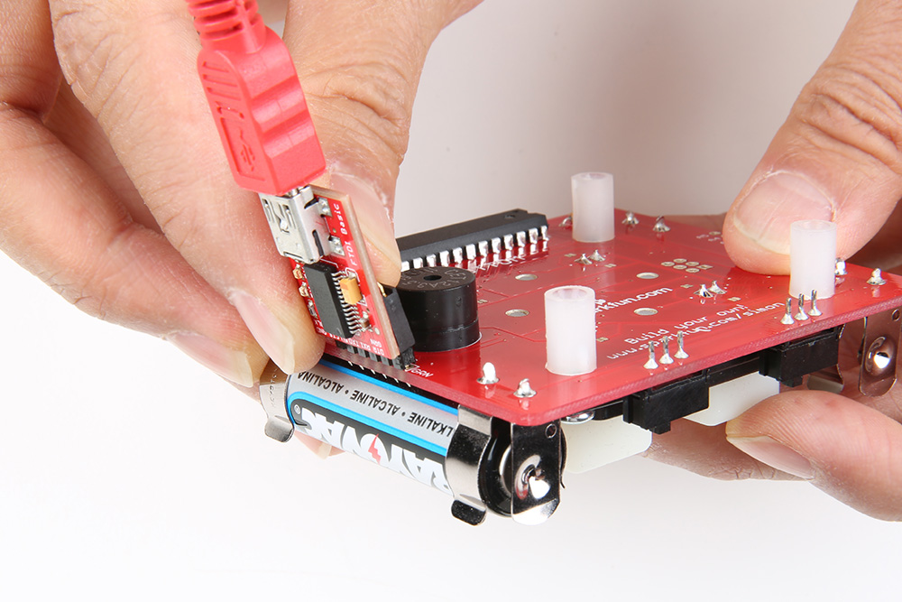
To reprogram your board, you are going to push the 6-pin header (that is already plugged into your FTDI board) into this port. You will have to hold it at an angle to cause a temporary connection. You will also need to make sure you align it properly. If you flip your board upside down, then you should see that the holes are labeled with some white ink. Look for the two pins labeled, “GRN” and “BLK”. These indicate the proper alignment of your FTDI board so that it is GRN to GRN and BLK to BLK.
The Simon Says board is programmable via the Arduino IDE. If this is your first time using an Arduino, please review our tutorial on installing the Arduino IDE.
If this is your first time using an FTDI, please review our tutorial on installing the FTDI drivers for your operating system.
Now that you've got your hardware setup, it's time to go back to the Arduino software and re-program your Simon Says Board. Before we can start re-programming there are just a couple settings we need to change in the software.
First, click "Tools" from the menu at the top of the window. Then follow the options to select Tools>Board>LilyPad Arduino w/ ATMega328. This is so that the Arduino program knows that it's talking to a Simon Says board (the Simon Says board and this LilyPad have the same chip).
Next, we need to tell Arduino which COM PORT we are going to use. (This is the communication channel that your FTDI breakout board is talking on). To do this, click Tools>Serial Port>COM4.
Make sure your Simon Says board's "Power" switch is flipped to the ON position with batteries.
As shown in the hardware assembly, hold your FTDI in place with the headers touching the plated through holes during upload and click on the “upload button” using any of the example codes provided in this tutorial. The upload button is the circular button at the top of the window with an arrow to the right. As long as there is sufficient contact between the header pins and the plated through holes, the compiled example code will be able to upload to the Simon Says board.
At this point, I would like to mention that any piece of code written in the Arduino IDE (such as the examples in the download above), are more commonly referred to as a "Sketch". The sketch is essentially a text document that you are writing and editing code within Arduino. When saving code in the Arduino IDE, it is saved as a *.ino file and called a "Sketch".
We have written 4 example pieces of code that can be used on the Simon Says Board. You can download them here:
After downloading, unzip the files to your computer.
On your Arduino window, click on File>Open... from the upper menu. Navigate to the folder with the example Simon Says code. This will probably be in your downloads folder similar to this directory: "C:\Users\...\Downloads\Simon-Says-master\Simon-Says-master\Firmware\Additional Experiments". Since we are testing out the first example, click on the folder labelled “SIMON_1_BLINK”. Now double click on the file titled, “SIMON_1_BLINK.ino”. This file contains the Sketch (a.k.a. example code).
You should see a new Arduino window pop up with the sketch inside the Arduino IDE's editor window. Click on the upload button in the Arduino IDE, give it a few seconds, and you should see a LED begin to blink on your Simon Says board.
If so, congratulations!! You just successfully uploaded a new piece of code to your Simon Says board!!
Try opening up the Simon Says experiment example 2. The file is titled, "SIMON_2_BUTTON.ino". Upload the code to your board.
Try hitting the buttons. Pressing one of the buttons will change the state of an LED from OFF to ON. The LED will turn OFF after one second until the button is pressed again.
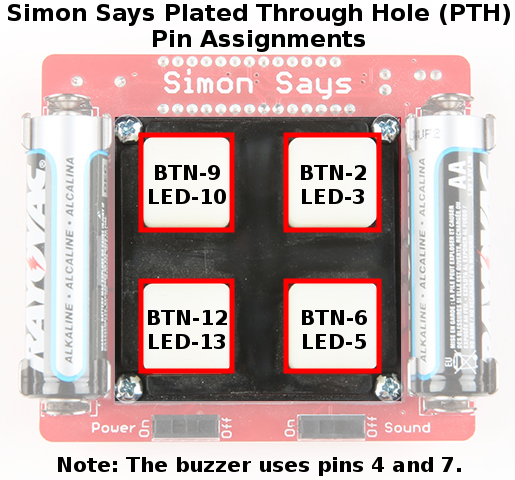
Again, you can read the grey comments to get a better understanding of how the code works. Try experimenting with the code to see if you can change the way the Simon Says board reads the button or turns on the LED. To help you out with hacking the Simon Says, here are a few notes about the pin locations of the Simon Says Plated Through Hole (PTH) version:
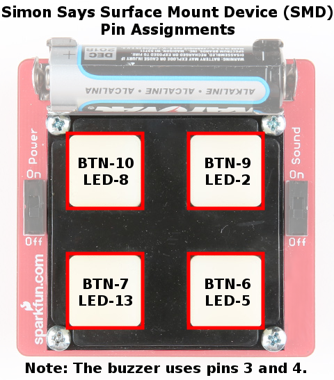
If you happened to get the Simon Says Surface Mount Device (SMD) version, the pin assignments are a little different. Here are the pin locations of the SMD version:
Try opening up the other Simon Says experiment example 3. The file is titled, "SIMON_3_BUZZER.ino". Upload the code to your board.
Try hitting the buttons. Pressing one of the buttons will light the LED and trigger the buzzer to play a few notes. Make sure that the Sound switch is flipped to the "On" position.
Again, you can read the grey comments to get a better understanding of how the code works. Try experimenting with the tone() function to see if you can change the way the Simon Says board plays a note. If you happened to get the Plated-through Hole (PTH) version: pins 4 and 7 are tied to the buzzer. If you happened to get the Surface Mount Device (SMD) version of the Simon Says, the pin assignments are a little different: pins 3 and 4 are tied to the buzzer.
This part of this tutorial requires a couple more pieces of hardware and a soldering iron.
Using these parts and a little bit of code, we can detect light. This will be useful in detecting whether the lights are ON or OFF in a room. In the Disco Mode example code, we will have the Simon Says board only go into Disco Mode when the lights are off – when it's time to get your boogie on!
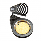
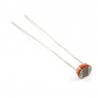
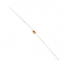
First off, let's take a look at the two components. Do you recognize that resistor from building your Simon Says? It's the exact same component you soldered into place when you built up your kit!!
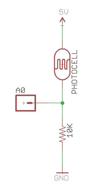
Next, let's take a look at the schematic for the light sensing circuit! Don't be scared – it's actually quite simple! A schematic is a drawing that represents physical things. It shows us how we are going to connect the two components to the Simon Says board. The green lines represent “nets” or connections. The other symbols represent actual things (like the photocell and resistor). The last three things in the schematic represent pin-outs on the Simon Says board. (GND, A0, and 5V).
Let's find these 3 holes on the Simon Says board. They are located on the bottom side underneath one of the batteries.

Next, let's twist the Photocell and resistor together in a way that will work with the schematic. Notice in the schematic how A0 is actually connected to both the photocell and the resistor. In order to solder this connection, it is helpful to twist one leg of the photocell and one leg of the resistor together. Make sure that there is enough room to insert the twisted pins into analog pin A0 before soldering.
Now we have essentially 3 legs that will solder into 3 pinouts on the Simon Says. Before we begin to solder, please check out this picture below that shows how the legs should connect to the Simon Says.
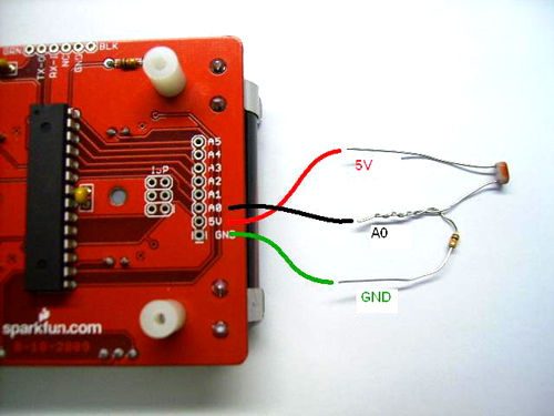
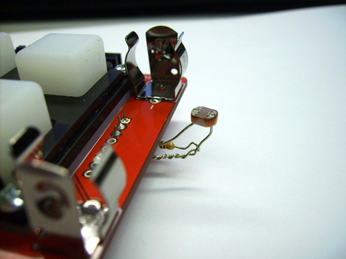
Notice how 5V and A0 are going to have to overlap. Be sure to remove your batteries before you start soldering. When you are finished soldering them into place, it should look something like this:
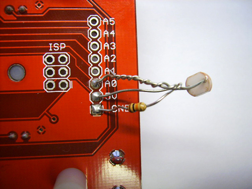
You can bend it around the edge so that the photocell is facing up and will do a better job of detecting the light. Like so:
You are almost ready to upload the Disco Mode Code! First, put your batteries back in and turn your board ON. Then open up the Arduino Software and open "SIMON_DISCO_MODE.ino". While holding your FTDI in place, click the upload button.
After the code is on there, try killing the lights and see if disco mode starts up!! If so, congratulations! You have just successfully completed your first embedded electronics project!
If you'd like to get your Simon Says back to playing the original game, head to the directory ".../Simon-Says/Firmware/Simon_Says". The "Simon_Game_Code.ino" will have the same default example code that we pre-program the chips with before they are packaged up in the kit. Make sure that the "hardware_versions.h" and "pitches.h" files are in the same folder when uploading.
Try browsing the additional examples in the Simon Says GitHub Repository written by SparkFun customer Mike Soltys. If you are interested in learning more about code, we also recommend looking at some of the example sketches that come build in to the Arduino Software. In the Arduino IDE, click File>Examples>Basics. You can also browse any of the code used in our SparkFun Inventor's Kit. All of the examples have good comments that will tell you a lot about how the code works. But most importantly, we hope that you can start working on a project of your own. We find that most first time makers have more fun and are most motivated when they have a specific goal in mind.
One creative lady at a past workshop planned to make a night-light that says "goodnight" with a unique sound and light sequence. Another person wants to use the Simon Says he built up to control the temperature of his custom made coffee maker. Or maybe you can combine the Simon Says board with some magic. At SparkFun AVC 2013, the buttons on the Simon Says were replaced with trampolines to trigger a dunk tank drop.
If you can think of a project that you would like to create – whether it's a night light or sophisticated self-destructing robot – this will help you stay focused and you will be amazed how much you can learn along the way!! What will you do with yours? The sky is the limit!! Happy Soldering!
Need some inspiration for your next project? Check out some of these related tutorials:
learn.sparkfun.com | CC BY-SA 3.0 | SparkFun Electronics | Niwot, Colorado