SHT15 Humidity and Temperature Sensor Hookup Guide
This Tutorial is Retired!
This tutorial covers concepts or technologies that are no longer current. It's still here for you to read and enjoy, but may not be as useful as our newest tutorials.
 Joel_E_B
Hooking It Up
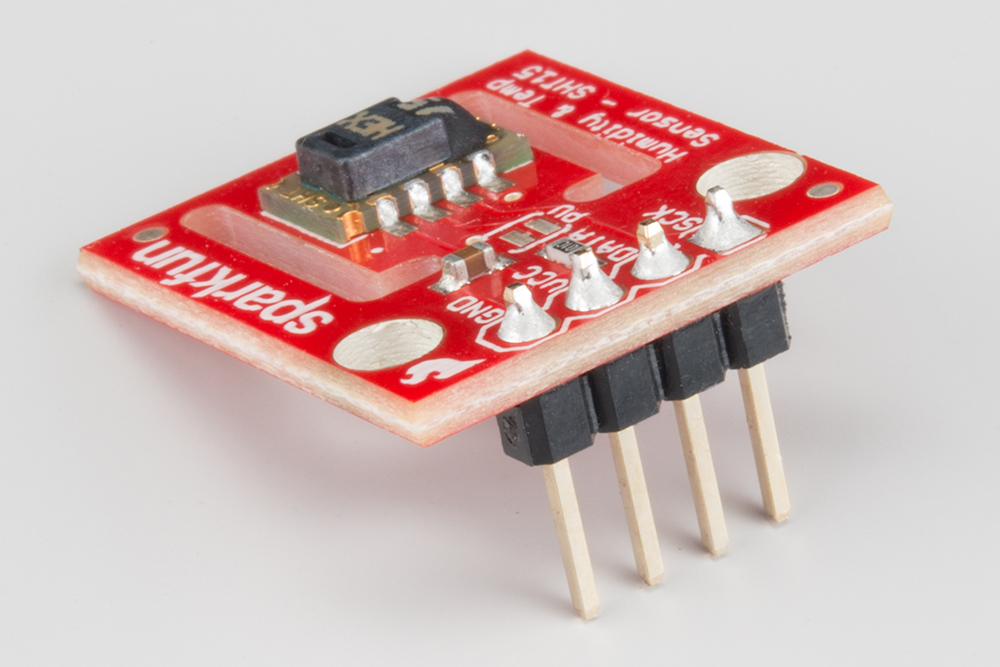
Wiring up the SHT15 is very easy! We recommend soldering four male headers to the breakout board. You can then attach it to an Arduino or Arduino-Compatible Board, such as our RedBoard.
Connections: Breakout board to Arduino
There are only four pins that need to be hooked up in order to start using this sensor in a project. One for VCC, one for GND, and two data lines.
- VCC → 3.3V or 5V
- GND → GND
- Data → Any I/O Pin
- SCK → Any I/O Pin
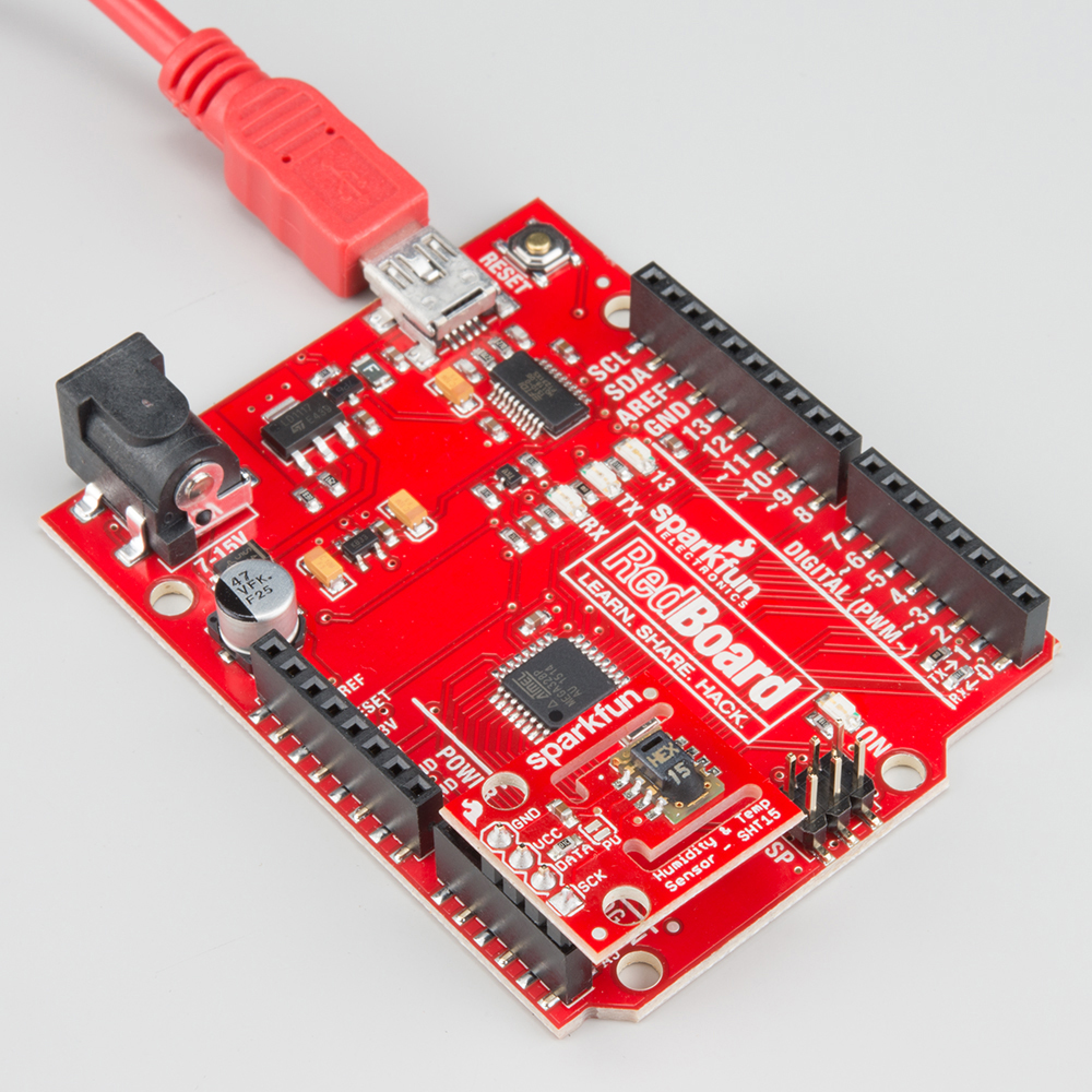
You can connect this sensor directly to the female headers on your Arduino like so...
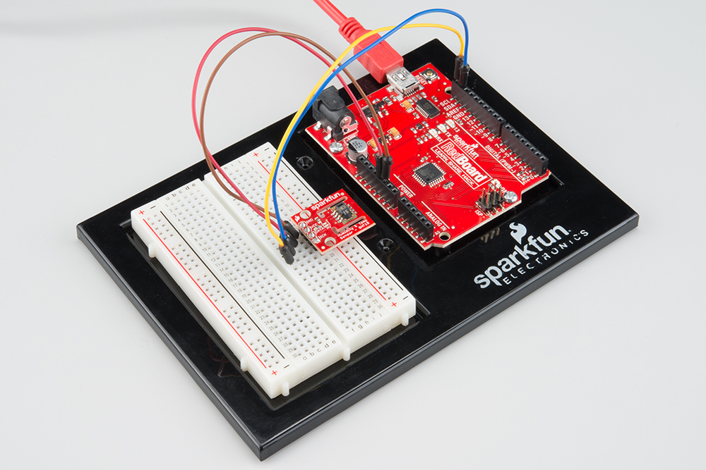
Or, you can wire it up on a breadboard.
2-Wire Interface
Please note that the SHT15 has a 2-wire interface that is similar to I2C but is NOT I2C. You may use the SDA and SCL lines to communicate with this sensor so long as they are connected to A4 and A5 on your Arduino or Arduino compatible board. You may use any other I/O pins for the Data and SCK lines as well.
Multiple Sensors
Unfortunately, the SHT15 has its address hard-coded, making it non-addressable. As a result, you may not have more than one SHT15 hooked up to any two pins at a given time. The 2-wire protocol used for this sensor does not allow for multiple of the same sensor to be on the bus, but it does allow multiple I2C devices to share the same bus as the SHT15, as mentioned above. In order to use more than one SHT15, you will need to use a dedicated pin for each sensor's Data line. You may share the Clock (SCK) line between multiple sensors. For example, you could have one sensor's Data line connected to pin 8 and another connected to pin 7, while both are sharing pin 9 as the SCK line. Declaring this using the library mentioned in the next section would look like this:
language:c
//Create two instances of the SHT1X sensor
SHT1x sht15(8, 9);//Data, SCK
SHT1x sht15_2(7, 9);//Data, SCK
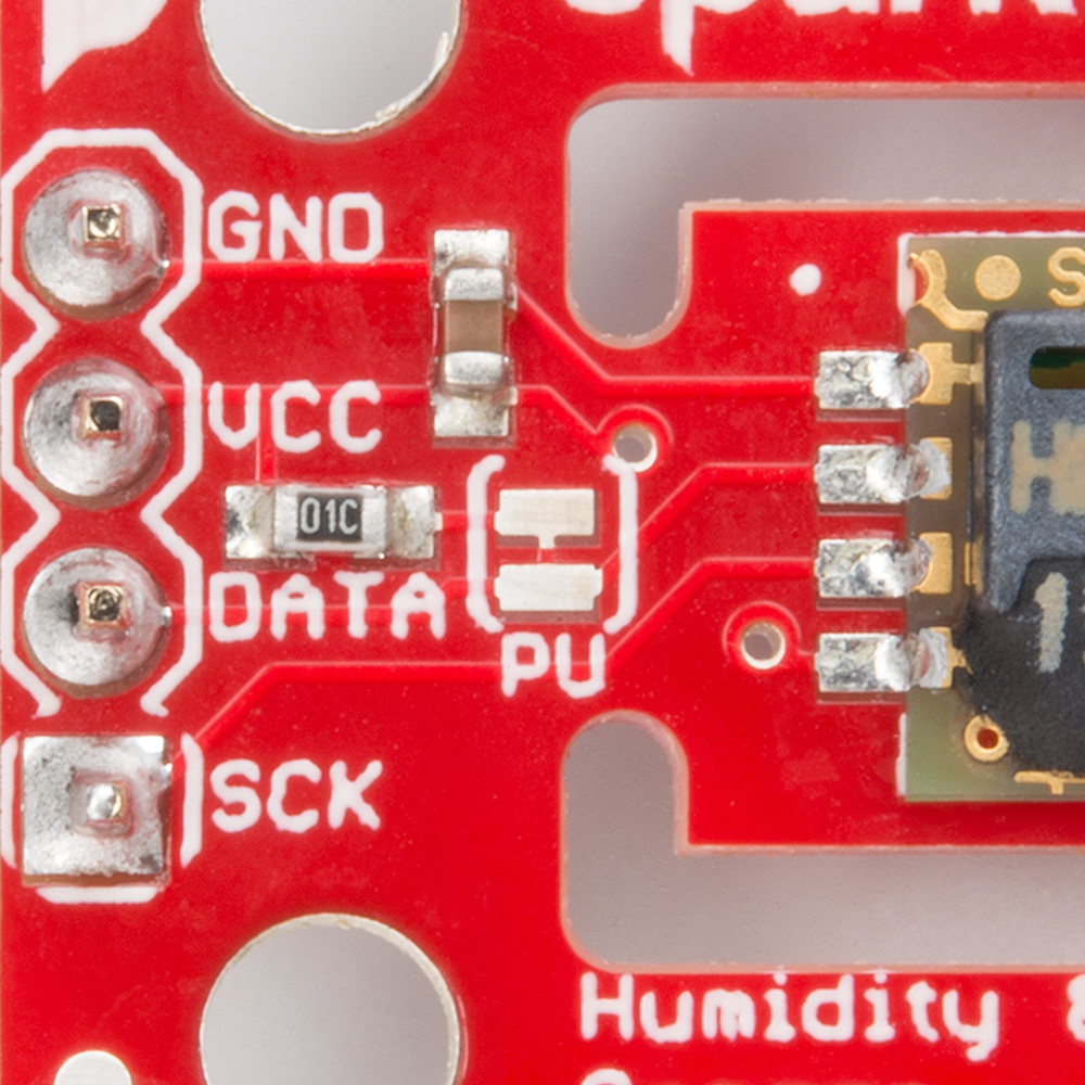
Pull-up Resistor
As suggested in the datasheet, a 10KΩ pull-up resistor was added to the Data line. Should you find yourself in a situation where you want this sensor and another I2C sensor with pull-up resistors to share the I2C lines, you may cut the trace in between the solder jumper labeled PU. If you ever need that pull-up again, simply place a blob of solder between the two pads.