Introduction
The purpose of this project is to show that milling is a complex, multi-layered and multi-step process. It's not like printing on paper; there are many small steps involved to get from an idea to an object. But, one must begin somewhere.
This guide is intended to allow someone who's never milled before make something useful with a mill.
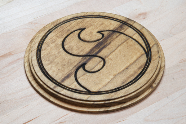
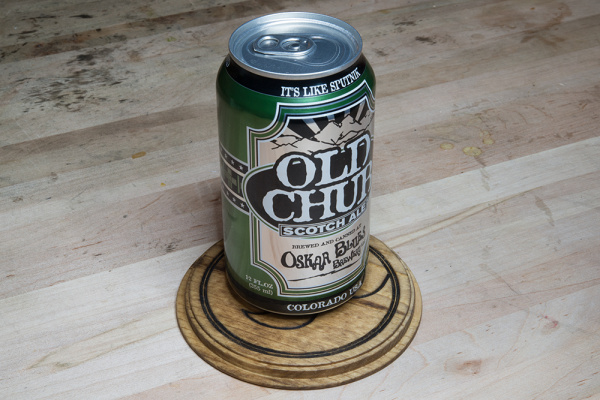
The finished coaster.
Tools needed
- Shapeoko mill (prototype shown in pictures), Stepoko controller, and a trim router
- 1/4 inch dual fluted wood router bit (from hardware store)
- 1/4 inch, 45 degree engraver bit (from hardware store)
- Drill for drilling and driving screws
- A drill bit to match screw shaft size
- The router chuck tool and adjustable wrench
- A few screws to hold down the material
- Hearing protection
- A computer that can get sawdust on it
Think about cleanup before you begin too. I operated outside but still had to vacuum down the mill and computer afterwards.
Materials
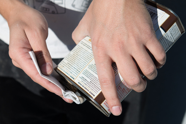
- Stain -- I chose Watco Danish Oil
- A Sakura brush pen
- A length of 1x6 Common Board
- Sandpaper
- Paper towels
Software
Suggested Reading
If you have not already, we recommend reading the Shapeoko Assembly Guide and the Stepoko Hookup Guide for a better understanding of how this project came together.
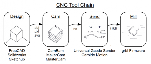
The first part of the process involves doing the design and CAM work. For this example, Inkscape is used to generate .svg files that are then passed to Makercam.com to do the tool path generation. This section covers what that process looks like.
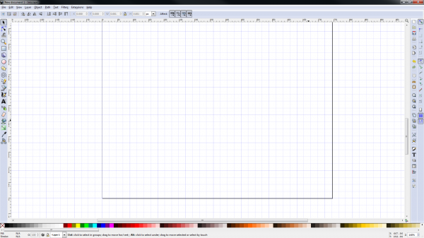
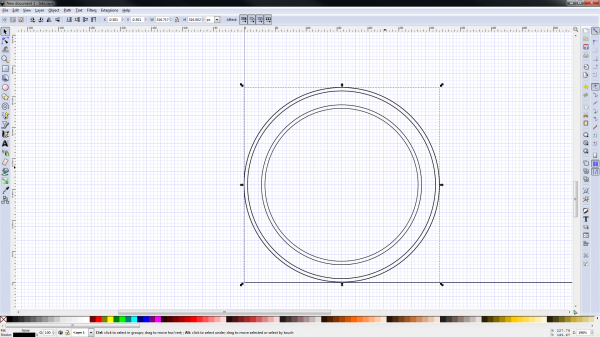
I start by opening inkscape and figuring out how to make the grid meaningful to me. I set it to 1/4 inch and aim for a 3 1/2 inch coaster.
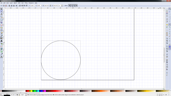
Start drawing some shapes!
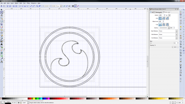
I realized my grid wasn't fine enough for the task, so I increased it. I put lines in for each place I want to engrave or cut out. I think I want two rings around the outside with a graphic in the middle, and a few terraced cuts around the parimeter
Now, it's time to bring in the graphic. Inkscape works great for dealing with vector shapes that don't have to be any particular size. On the flip side, it's not so good for working in strict coordinates, like for machining parts.
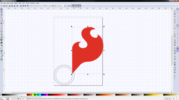
The SparkFun flame is the obvious demo material! After importing it, it needs to be cleaned up.
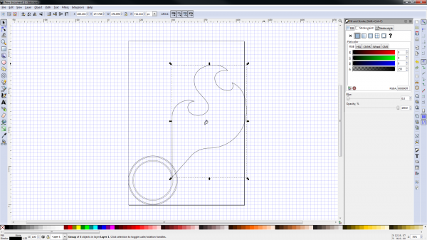
Select it, remove the fill, and set the stroke paint to solid. After this, a mini flame can be seen in the middle for no particular reason. Delete what you don't need.
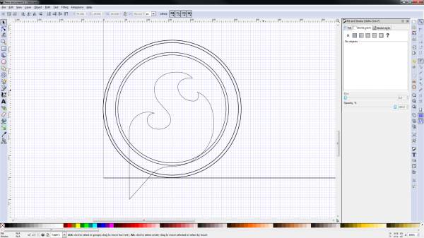
I thought the flame might look good framed by the two edge circles, so I scaled and slid it around until I was satisfied.
To remove the extra part, select "edit paths by node", and use the tool bar to clean up the desired points.
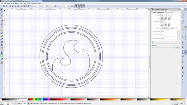
At the last moment, I decided I wanted to put another level to the perimeter. I had already made the interior graphics, so I slid up and to the right so I could put another circle around them.
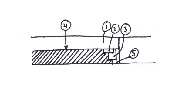
A sketch of the profile helps me decide what cuts need to be done, and in what order
I was developing this thought as I went through the inkscape drawing and came up with the above. Each number is the order of the operations. For the first job, the 1x6 will be planed down to 3/8th inch, and two of the perimeter cuts made. The coaster won't be free until step 5 which is what I want. The next job will be to change tools and run step 4 to put the graphics on the coaster. Lastly, the perimeter cuts will be finished releasing the part from the stock.
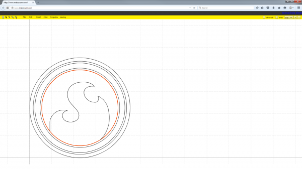
Now that I have an idea of what my workflow will look like, MakerCam is loaded with the .svg file from inkscape, and it appears at the origin because that's where I drew it. If it's not, it can be moved.
I've selected one ring to show that each line is an independent shape. If different operations happen for different shapes but they're connected, the CAM software can't tell them apart.
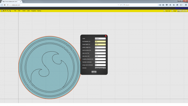
The first operation will be to plane the 3/4 inch stock down to the thickness of the coaster, 3/8 inch. Select the major circle, then select 'CAM' then 'Pocket operation'. MakerCam presents me with a set of parameters that I need to change. I know I'll be zeroing the machine to the surface of the material, so the stock surface will be 0. I'll cut down to .375 inches, or -0.375 (because down is negative on the Z axis). Feed rates and depth-per-cut can be set here too. Don't forget to specify your tool diameter!
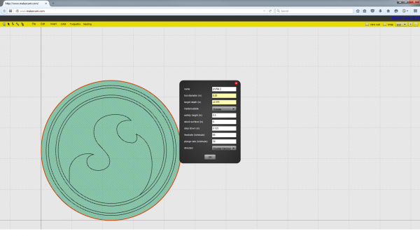
Next up is to make a profile operation. This will generate a path around the major circle to hog out the extra material and give the tool some room to work on the other parimeter operations. Really, this just makes the pocket operation a little bigger.
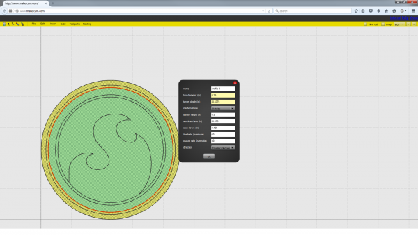
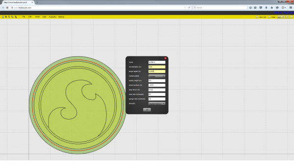
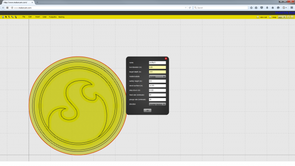
Now, it's time to make the two profile operations that make the detail on the perimeter. First, a shallow cut on the inner circle, then a deeper cut farther out.
This is the profile for the outer circle.
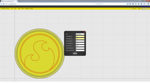
To make the toolpath for the engraving, select all shapes to engrave (use ctrl-click to multi-select) and choose 'CAM' then 'Follow path operation'. Where a profile operation is used, the path goes outside or inside the line by half a bit width, while 'Follow path' goes directly on the line. I will be using a fine pointed engraver for this step so it's Ok, I can assume the width is small. I've set up these parameters to make one pass at almost the complete depth, then finish off with another pass a little deeper to make sure everything is cleaned out.
The final operation is to finish the parameter cut and free the piece from the stock. When the part becomes free, it may bounce around and get chewed up by the tool but I'll risk it. Using 'tabs' is the industry standard way of cutting out most of the part while leaving little bits of material to retain it. Tabs are available in MakerCam, but I haven't used them.
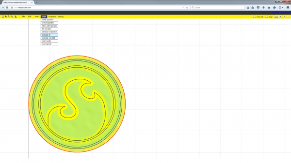
Now, click 'CAM' then 'Calculate All' to have the software ponder the operations you have specified and generate the associated tool paths.
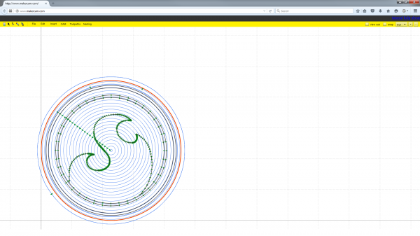
After calculating, green paths with arrows appear that show the movement from the top down. Everything *looks ok, though our view is obscured by the lack of a third dimension.*
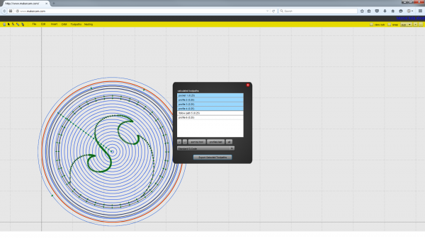
Here's where the Gcode comes into play. Select 'CAM' then 'Export Gcode' to bring up this window. It allows you select which operations go together, then generate and save a text file. Don't forget to add ".nc" to the end of the file name for MakerCam! The first job I select will be steps 1, 2, and 3 of my profile diagram, which will include the first pocket, the major profile, and the two detail profiles.
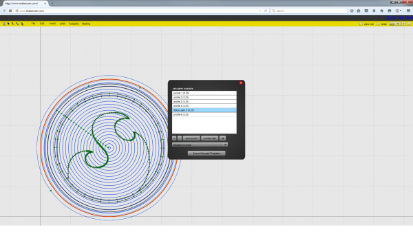
Next up is to export the engraving step on its own. This is because I need to manually change tools, and I can't do that in the middle of a Gcode job.
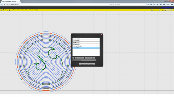
The last thing to export is the final perimeter cut.
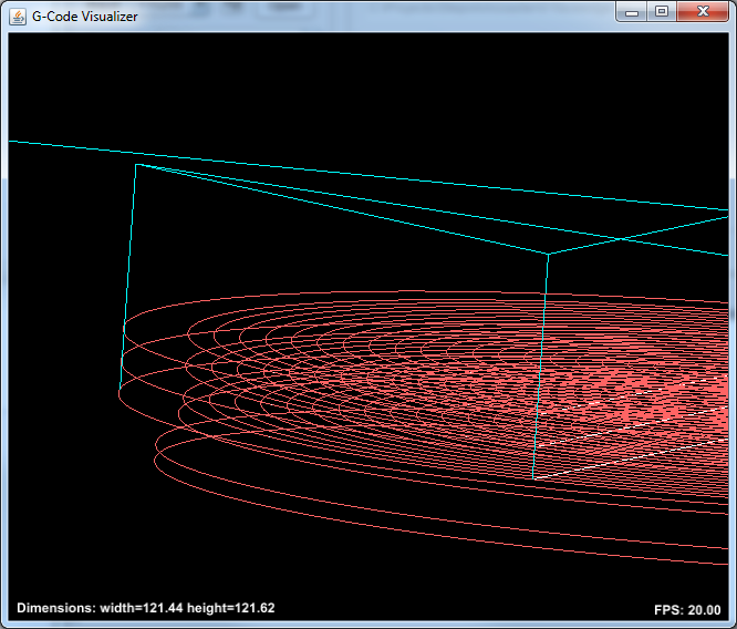
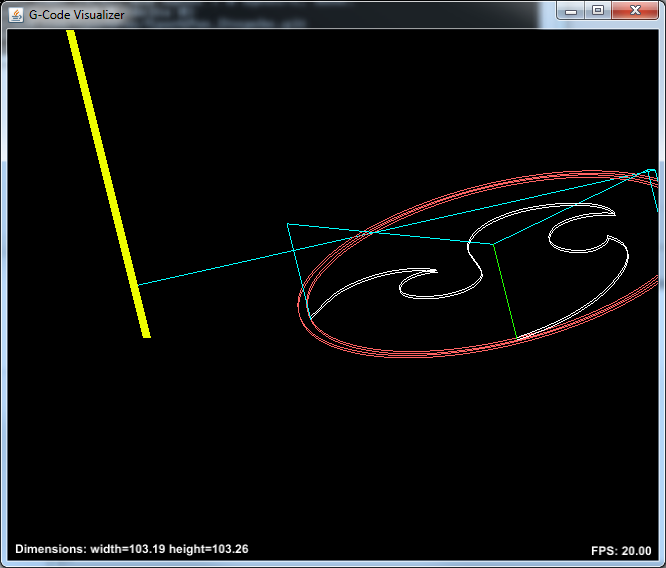
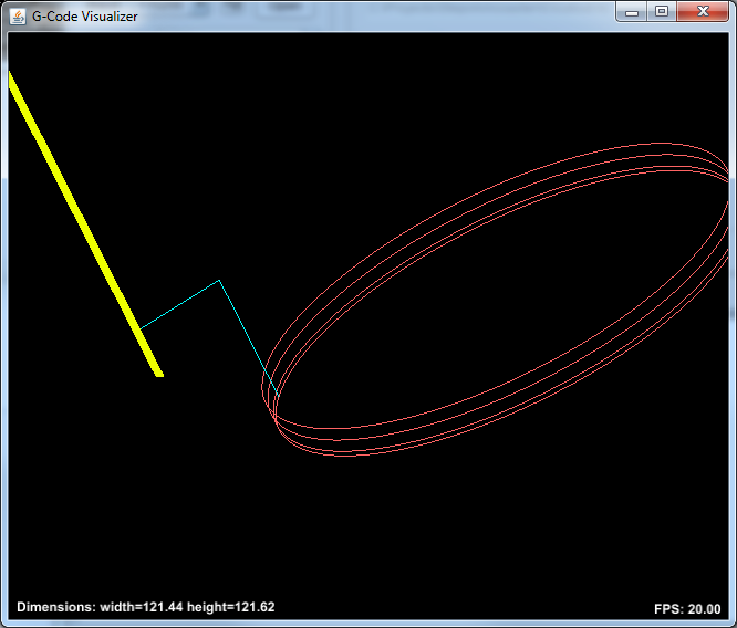
Now, I have three .nc gcode files! As a sanity check I open them in Universal Gcode Sender, and click the 'visualize' button to view the paths in 3D
The first path shows mostly pocketing with a few parimeter paths, just how I want it. If you look closely, you can see how they will create a stepped edge.
The engraving step looks good too. It has two closely spaced cuts that resemble the original graphic.
The final pass to release the part. Notice that when the last cut is made, the part will not be held to the wasteboard anymore and will have be retained with a push-stick for a good cut.
Operating the Mill
Setup
Now that the files look good, it's time to prepare for the actual work. Gather together all the things you think you'll need before starting, especially if you're not working in a shop. This can prevent running for new tools.
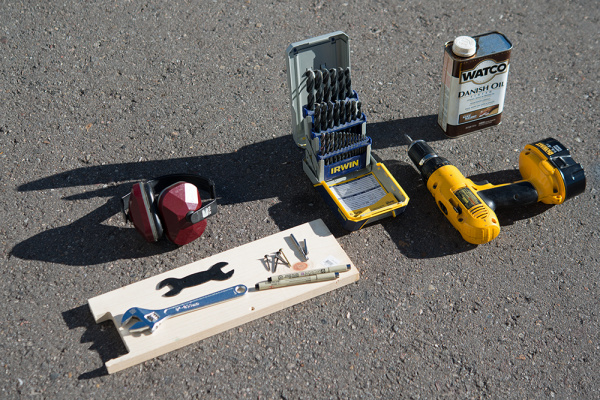
The various hand tools and supplies collected for this project, as mentioned in the Introduction.
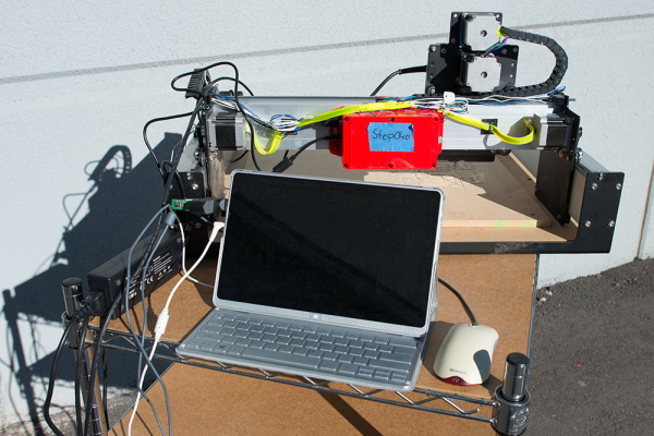
Of course, you'll need a mill and computer. Shown here is a Carbide 3D Shapeoko mill with SparkFun Stepoko controller
Operation
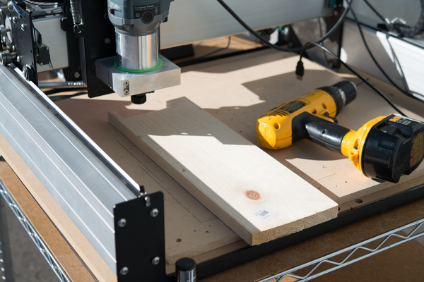
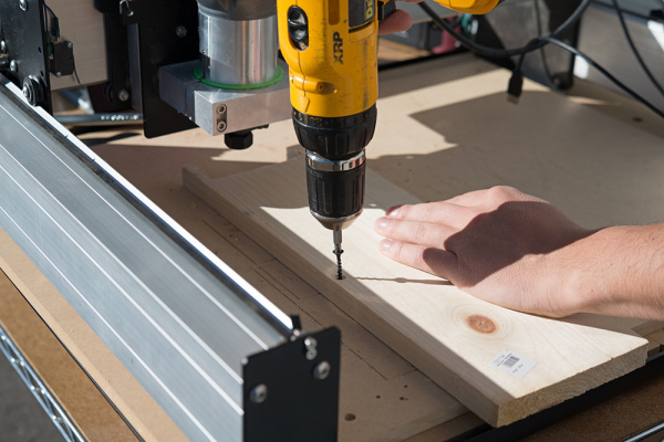
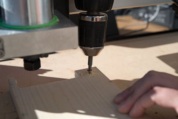
Set the material into the mill. Some mills have clamps but for this simple job I drilled holes in the material and screwed it down to the wasteboard.
I've left the carriage at about zero so I know the cut path of the job won't hit the screw heads. An easy way to get it all straight is to eye-ball off the previous liner cuts that develop in the wasteboard over time.
There will be three jobs to run. First, 1/4 inch milling, then engraving, then milling again. With the e-stop enabled, the carriage moves freely but doesn't track motion. We haven't calibrated to zero yet, so move it up to get to the collet.
The tool is made pretty tight. If it slips up in the collet during operation, the tool may be dull, too loose, or the feed rate is to high.
Now, it's time to make a zero reference. Once made, this will be zero for all jobs. If everything goes smoothly (don't plan on it the first time around), the machine will never have to be re-zeroed. If not, you'll have to use this reference to locate zero again.
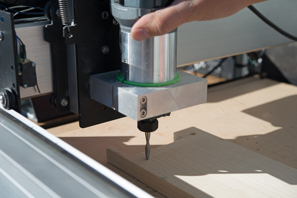
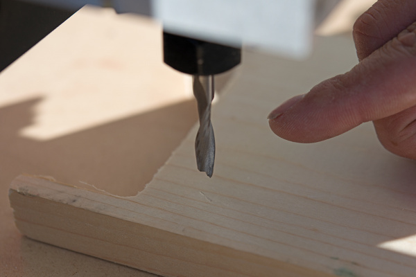
The tool can be lightly pressed into materials like plastic and wood to dent and give a mark.
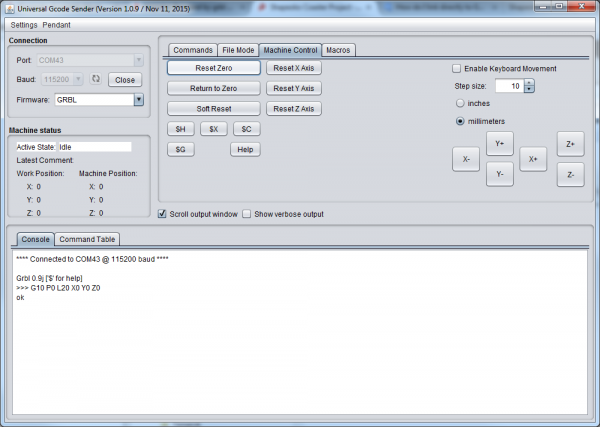
Back on our computer, click 'Reset Zero' to tell everybody that the machine is at the new zero. If this doesn't seem to take, close and reopen the software.
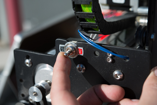
With the machine at zero, switch off the e-stop (turn on the switch). This locks the stepper motors.
Use the machine control tab in Gcode Sender to lift the tool by a know amount. I chose 10mm. This is kind of a sanity check to make sure the machine is working and to get it away from the material.
Lesson: Draw a cross-hair across the center of the zero. Later in the process, I dropped a running tool on the point and milled out the indentation and had to guess a bit. Pros use
wigglers to set zero.
Hearing Safety Warning!: High speed cutters are loud! Some people think it's not so bad, but after about a minute of milling they all start backing away. Put on hearing protection before proceeding.
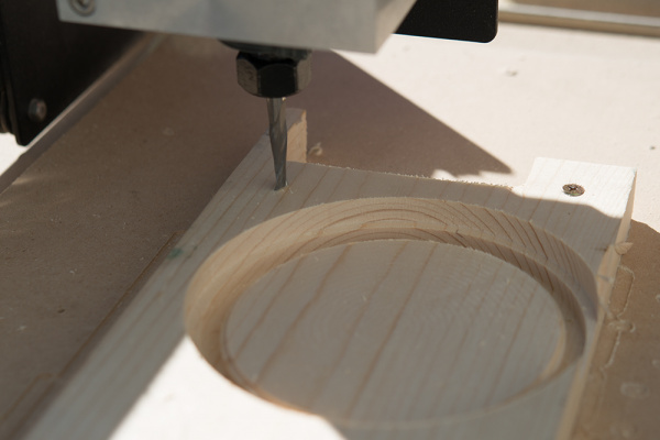
After the first pass, the first 3 operations are apparent. The mill has been returned to zero.
To switch tools, use the switch to unlock the motion, lift the Z axis without disturbing the X and Y, and re-enable the motion. Now I have some room to work.
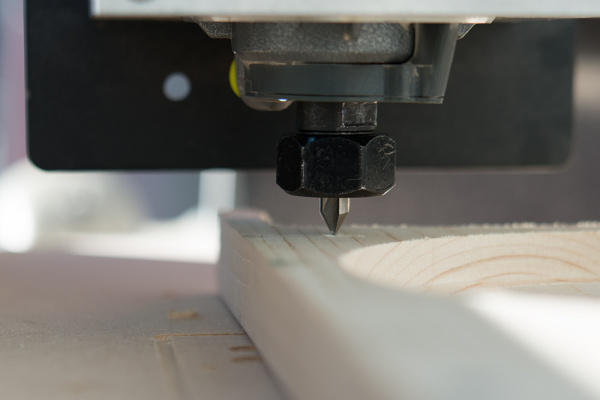
Oops! It can be seen here that the black plate, which moves with the tool, will crash into the work surface if I try to run the job.
Lesson: Make sure the tool is adjusted in the clamp before starting any work.
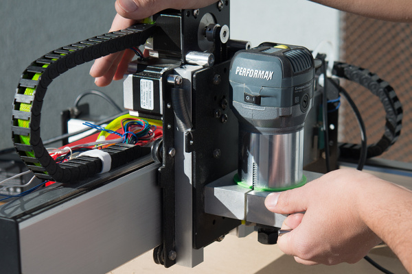
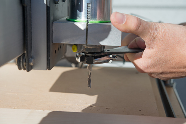
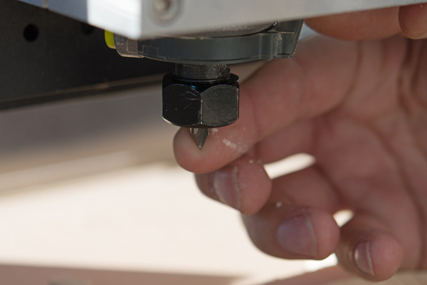
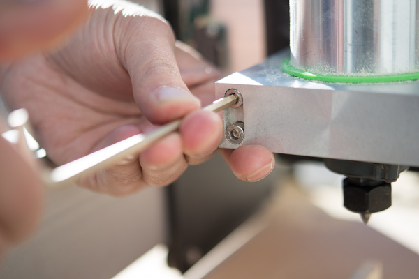
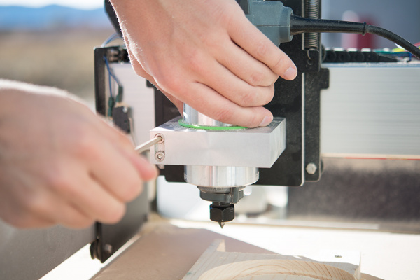
I loosen the router clamp evenly.
The router is dropped down an inch or so. I had to zero again before running the job.
After running the job, switching the tool back to the mill bit, and running the final perimeter job the part is released. If you watch the video you can see that on the last pass, I hold down the part with a scrap pushstick. Alternately, you can leave tabs in the CAM software so that it doesn't fly around when on the final cut.
Enjoy a time-lapse video of the three jobs being sent to the mill!
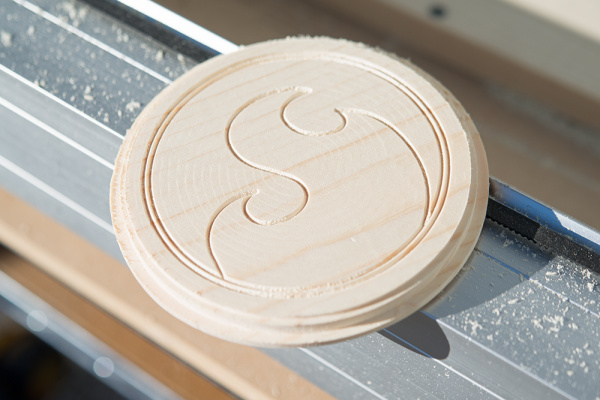
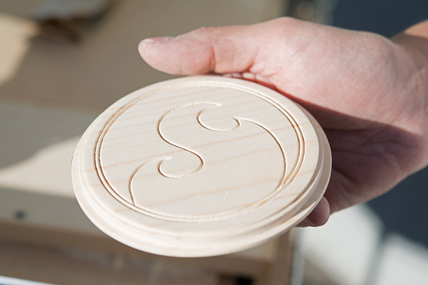
The coaster, right out of the mill.
Finish Work
Finishing work really brings out the design and is pretty easy to do for any woodworking project.
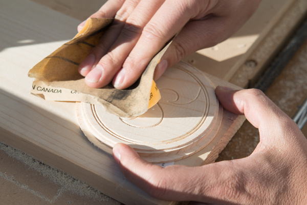
Sand the coaster to your heart's content! I used a medium grit paper in circular motions, and it came out as good as soft wood can.
Ahh, I'll take it!
This Danish oil is applied with a cloth or spounge... or paper towel.
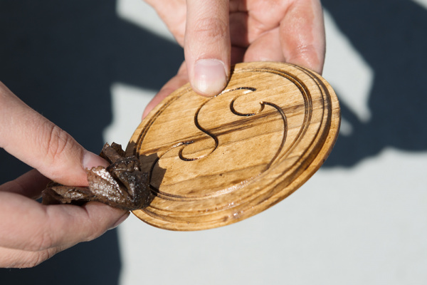
The idea is to apply profusely, let sit for 10-15 minutes in the shade, then wipe off the extra.
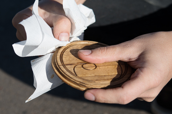
The coaster is wiped down to remove the excess stain.
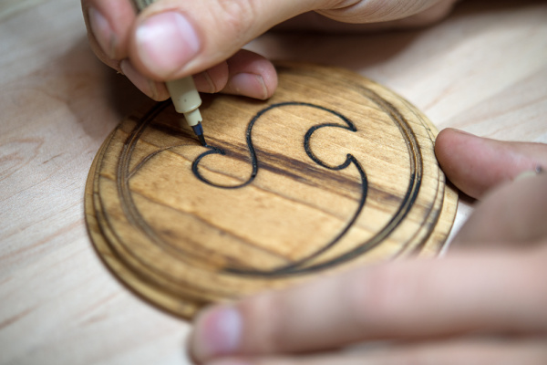
Carefully line the engraving with a brush pen such as this one made by Sakura.
