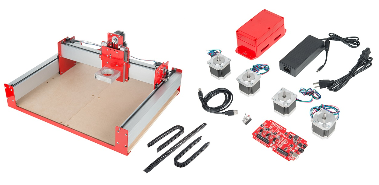
SparkFun's Deluxe Shapeoko kit is a Carbide3D Shapoko 3 in fancy SparkFun red with our open source 3 axis mill driver, the Stepoko.
This guide directs you to the Shapeoko assembly instructions, then goes through the final steps to add the electronics to the mill.
Stepoko Guide - This guide talks about how the Stepoko control electronics works. Important information is also linked below.
Follow the Shapeoko assembly instructions until you get to the part where controller is added. There are a few differences, for instance the motors in this kit have equal length wires, but nothing too significant. Use the parts list from downloaded from the "Required Materials" section above rather than the list from the assembly guide.
Install the Shapeoko into the enclosure. There are 10 4-40 screws for this purpose, but you'll only need 8. Use a number 1 phillips screwdriver.
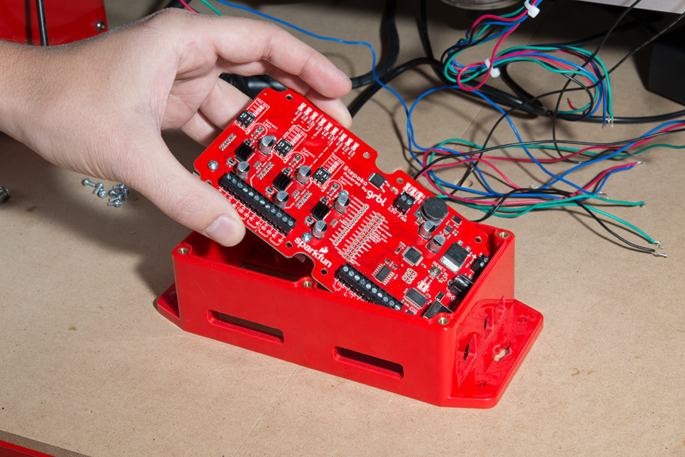
Get ready to install the controller. Test fit it first, but don't install just yet, set it down such that the pad can be added, and then it can be rotated into position. Make sure the aluminum heatsink and extruded mill rail are clean and free of debris.
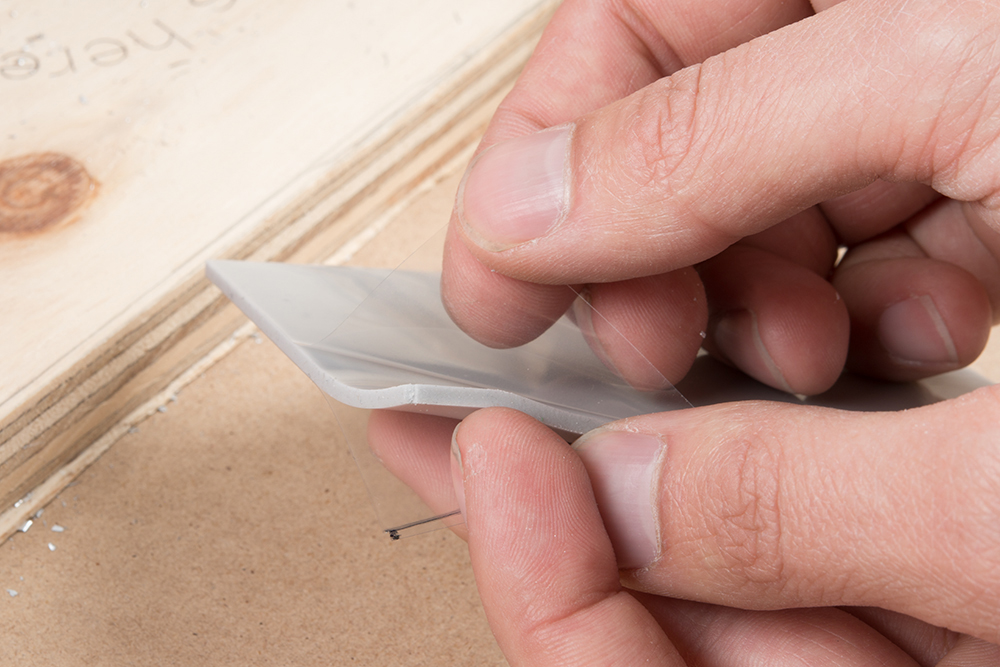
Peel one side's protective sheet away and discard. Both sides will be removed, but just peel one for now.
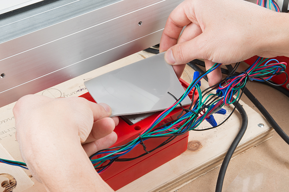
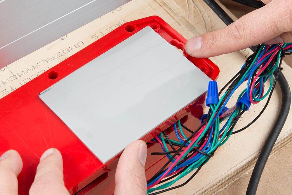
Holding by the corners, lower the pad onto the exposed heat sink, and gently press into place. Generally, it just needs to be centered and overlapping the edge of the heat sink. It's been sized so that the following two points can insure it's in the correct position:
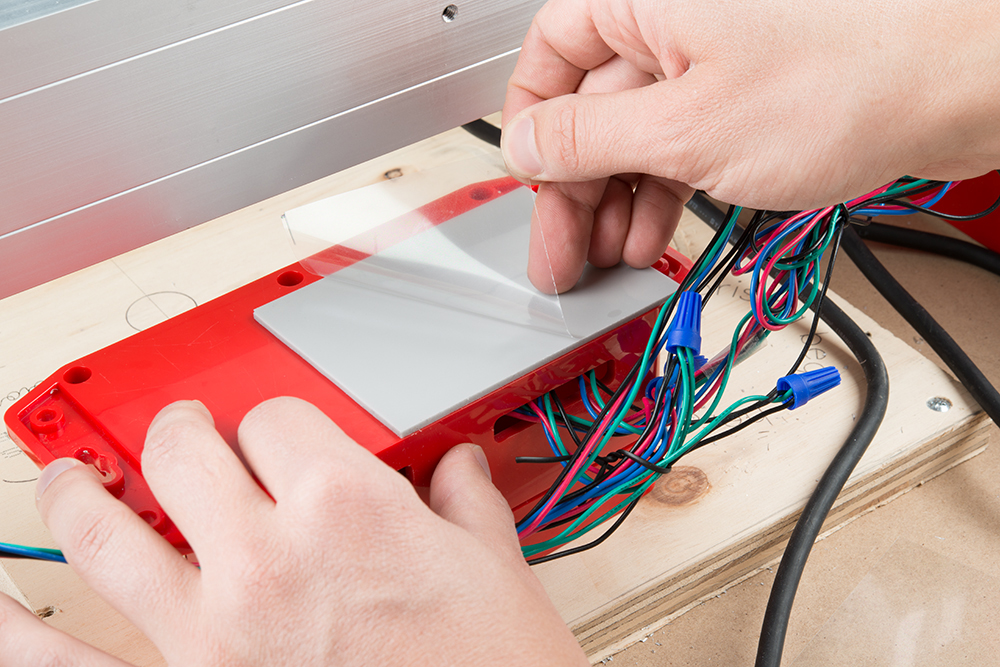
Peel the second protective layer away.
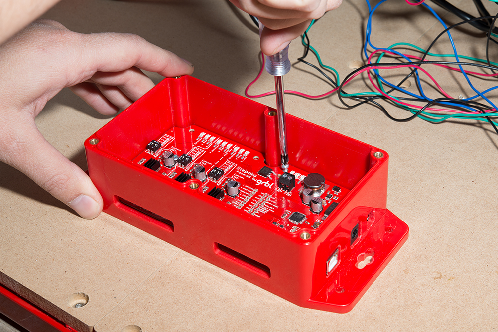
Install the Stepoko controller. The pad will add thickness and cause the enclosure to sit off the mill, so don't tighten the mounting bolts down too hard. Use threadlocker to keep the screw from backing out due to vibrations. Alternately, a flat washer that's slightly thinner than the pad can be used here.

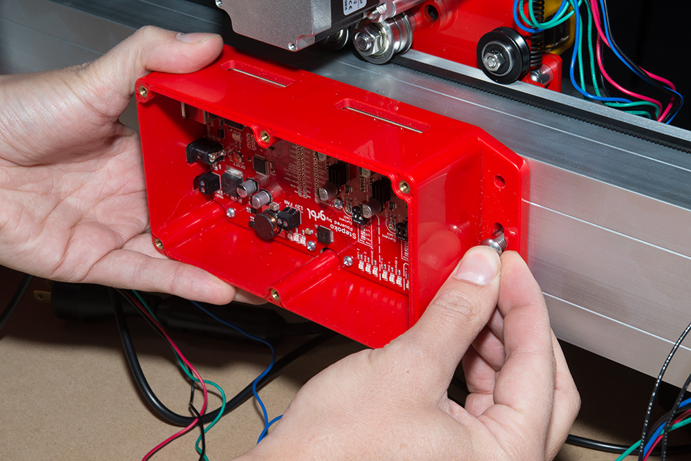
Install the enclosure to the rail with the terminal connections at the top. Use the extra M6x12mm bolts provided with the Shapeoko.
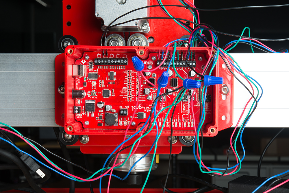
Connect the X and Z axes to the Stepoko. For more information, check the Stepoko guide's Hardware: Connecting the Motors section.
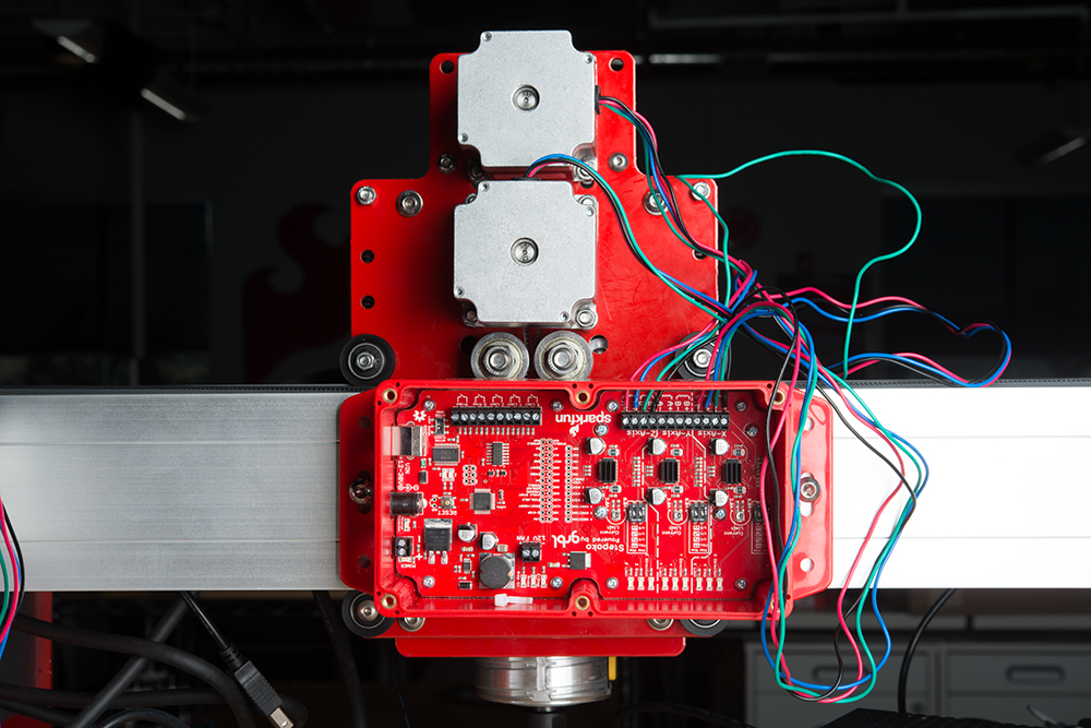
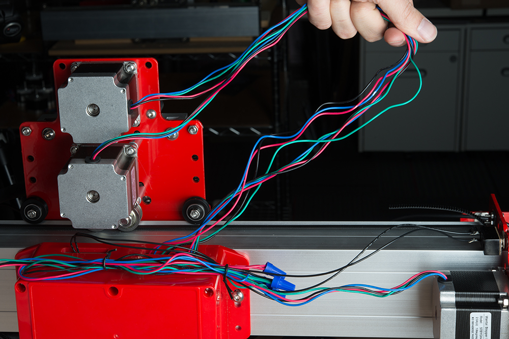
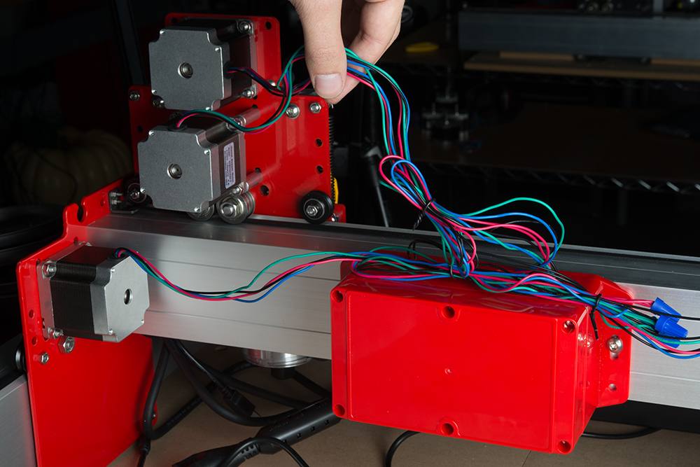
Connect the Y axis. But wait! It has two motors that are wired in parallel.
If two stepper motors are connected in parallel, they may not spin in the same direction because the internal polarities may not be the same. The solution to this problem is to transpose the colors of one pair of coil wires. This polarity/spin direction problem is compounded by the fact that the motors are mirrored on the mill and actually need to spin different directions.
Watch the video below go get a basic idea, then work through these steps.
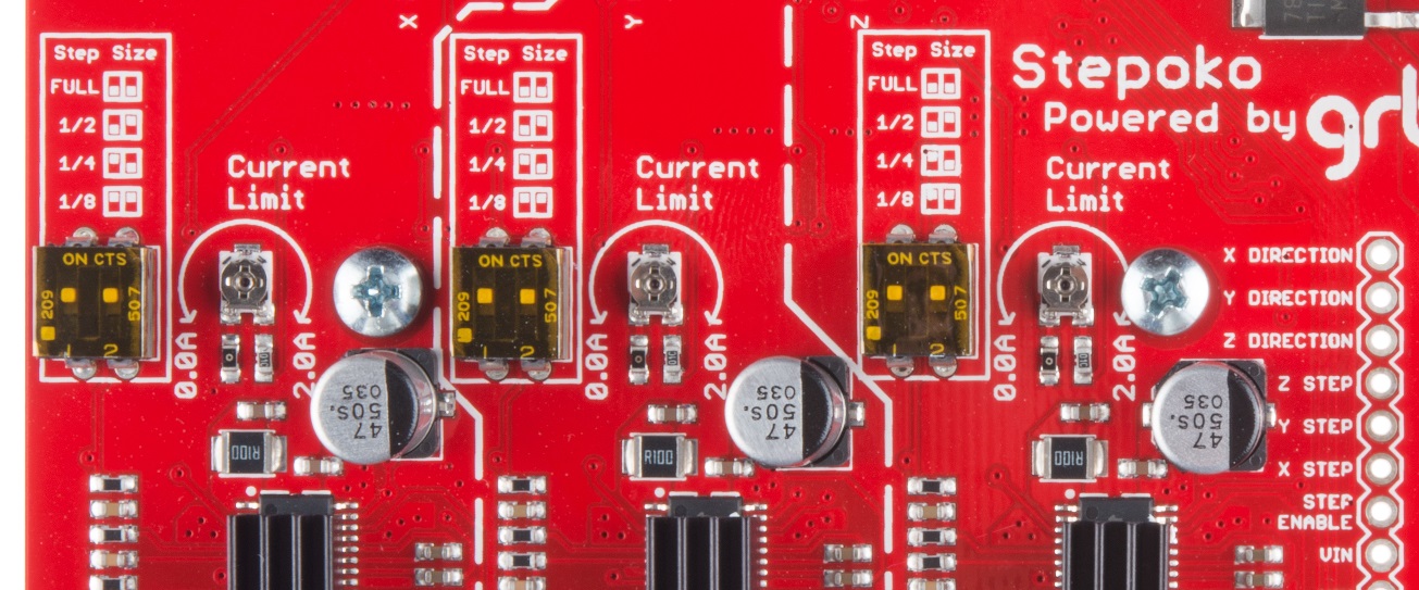
Set the motor drive currents. Make sure the trimpots are in the center for 1A service until you are more experienced. Or, read up on how the current setting works in the Stepoko Guide's Hardware: Setting the current section.
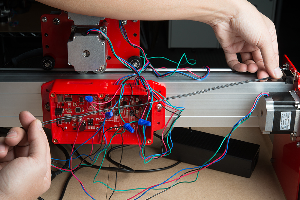
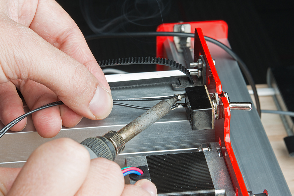
Mount the switch to a free hole on the gantry end plate and solder on leads.
Screw in the lid to the enclosure using a number 1 or 2 phillips.
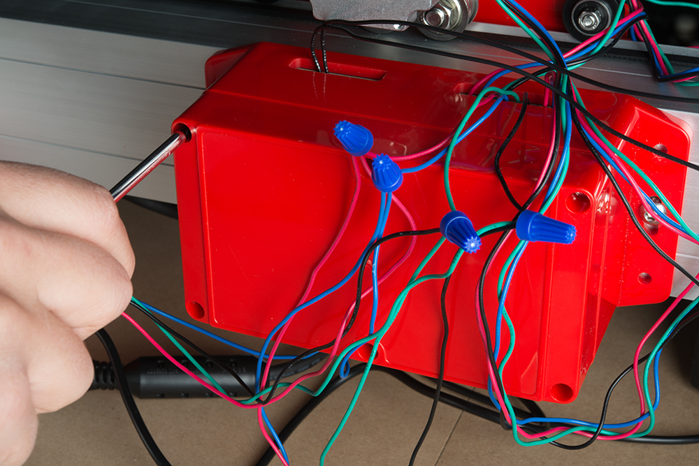
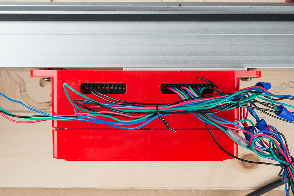
Collect your wires and bind with twist ties or zip ties.
Connect the power supply, power cord, and USB cord between your computer and the Stepoko
Open up the Universal Gcode Sender, open the Stepoko's serial port, and select the machine control tab. Set the switch to 'ON' and try to move the machine by computer control. If the axis move in the wrong directions to your liking (but of course, up should be positive Z), switch the direction bit field accordingly. Use the Stepoko guide's Software: Machine Control section for more information about grbl, or check out grbl's Github wiki for more information on changing settings.
Measure know movements and calibrate each axis. See the Stepoko guide's Firmware: Configuring grbl and Calibrating section for more info.
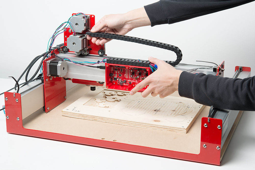
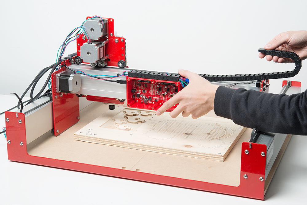
The cable carriers have been included in your kit to help with wire management, but it's up to you to decide what cables to carry and where you you would like them to be. They can go either way on an axis and don't need to be full length to get the job done.
This section shows the installation of a cable carrier between the mill head and the cross-rail. The process is the same for any axis.
Start by finding the location and length of the cable carrier. Hold the fixed end of the carrier in where you think it should go, and move the mill head through the full range to make sure the cable carrier has unrestrained motion along the axis of movement. Alternately, mimic the motion of the mill to approximately check the motion. The cable carrier should be shortened if there's not enough play in the wires or if the loop hangs too far off the mill.
 |
 |
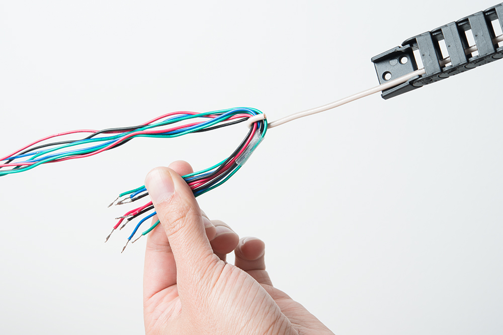
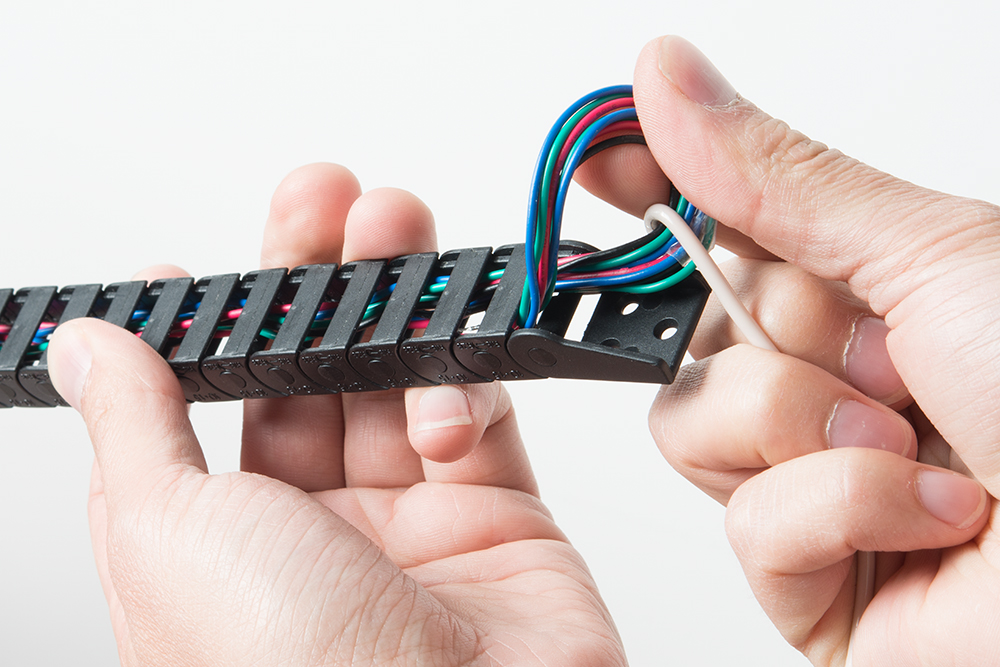
Pull the wires through the carrier. A hooked wire or tape on a straight wire helps. When running multiple groups of similar colors through, mark each set differently with sharpie or tape.
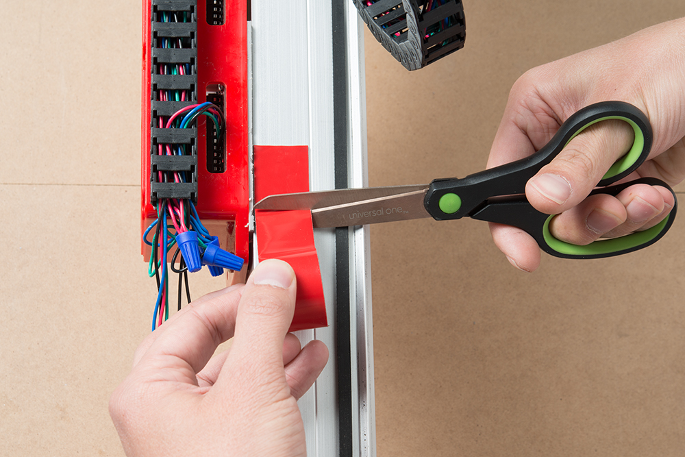
After you've located where the fixed end will be, cut a small piece of double-sided tape, and firmly squish the carrier down. For these Shapeoko mills, make sure nothing crosses the center line in the extrusion.
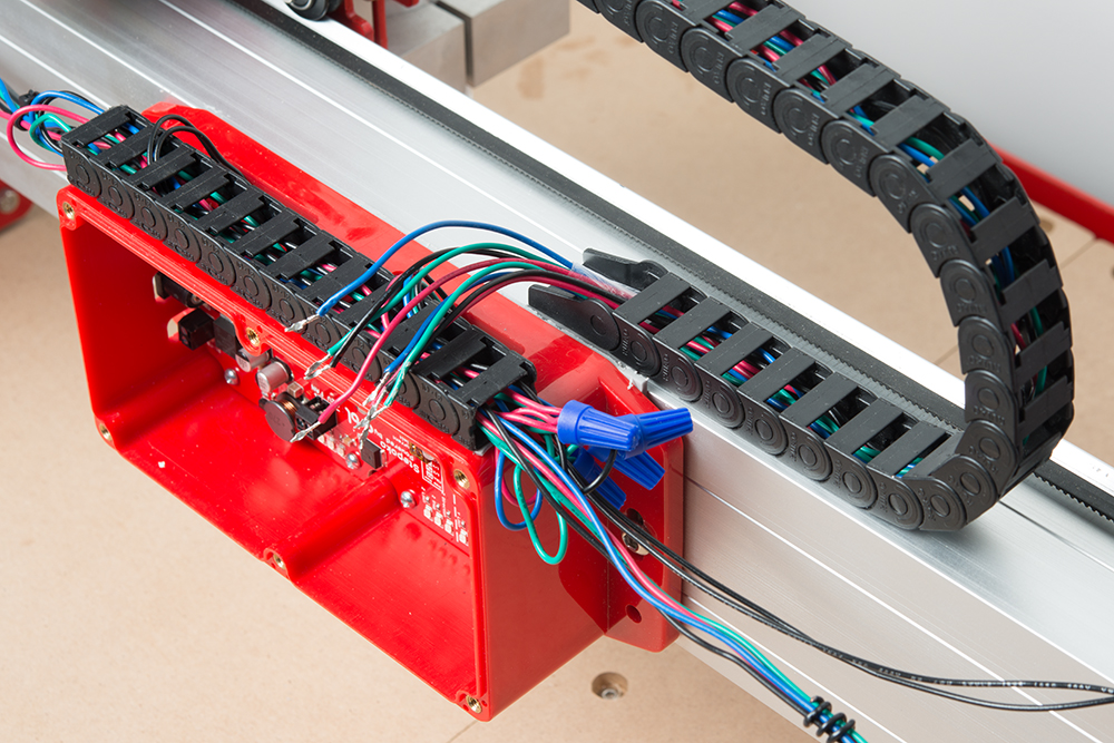
Check that the wires will reach the terminals, that the axis has a full range of motion, and that the roller bolt misses the cable carrier. Then connect the motor wires for the final time.

Here's some links and projects you may find useful.
Or, head back to the The Stepoko and Shapeoko Landing page to see what accessories and tools are available.
Now that you have built your Shapeoko Mill, check out these other SparkFun tutorials to learn how to use the SparkFun Stepoko Control board.
Once you're familiar with the Stepoko, create your first project by following along with the Shapeoko SparkFun Coaster.
learn.sparkfun.com | CC BY-SA 3.0 | SparkFun Electronics | Niwot, Colorado