Roshamglo Hookup Guide
 Alex the Giant
Hardware Overview
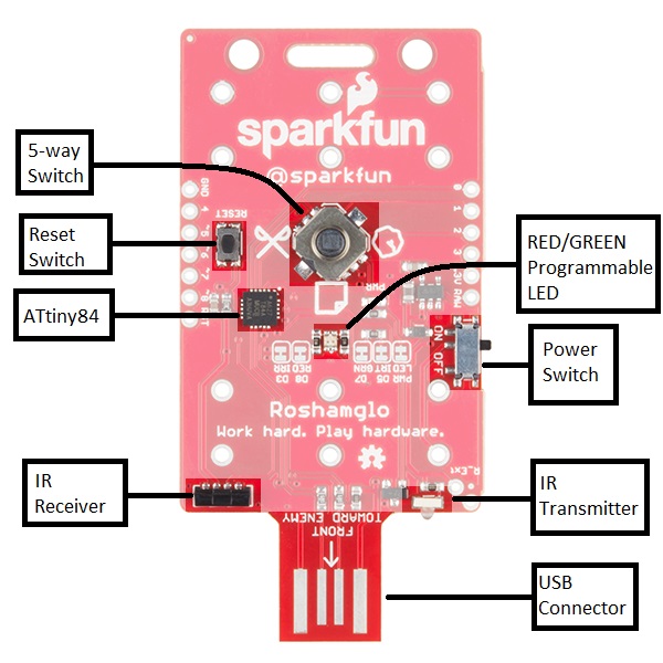
The Roshamglo uses the following:
- ATtiny84
- IR LED
- IR receiver with built in 38kHz demodulator
- USB programming
- Programmable red and green LED
- A switch for power
- 5-way switch for input
- Reset switch
- 6x AAA PTH battery clips
- 3x AAA batteries for power
The brains behind the Roshamglo is an ATtiny84, a light weight Arduino compatible microcontroller. The ATtiny84 comes with the following:
- 8kB of flash memory for our program (~6kB after the bootloader is installed)
- 512B of SRAM, which stores our variables used in our program
- 512B of EEPROM
- 12 IO pins MAX (the Roshamglo breaks out 9 of these pins)
- 10-bit analog to digital converter which can be used on 8 pins
For details about what each pin is able to do, refer to the table below.
| Pin | Analog or Digital | Additional Uses | Roshamglo Uses |
|---|---|---|---|
| 0 | Both | Analog Reference | 5-way switch down |
| 1 | Both | -- | 5-way switch right |
| 2 | Both | -- | 5-way switch up |
| 3 | Both | -- | IR Receiver |
| 4 | Both | SCK, SCL | 5-way switch left |
| 5 | Both | MISO, PWM | IR LED |
| 6 | Both | MOSI, SDA, PWM | 5-way switch center |
| 7 | Both | PWM | Green LED |
| 8 | Digital | PWM | Red LED |
Each of these pins have been broken out to edge of the board to make customization easy! If you would like to use any of these pins for something other than what it's currently connected two, we provided jumpers that can easily be cut with a hobby knife. The only pins that do not have a jumper on them are the pins used for the 5-way switch. The pins for the switch use the ATtiny's internal pull up resistors, so as long as the switch is not closed, the pin can be configured in any way you'd like without having to cut traces.
One important feature missing
If you hadn't noticed in the pin description, there was no mention of RX or TX pins. This is because unfortunately the ATtiny84 doesn't have a hardware UART. The UART is used for serial communication, whether it's for programming, or printing messages to the serial window. You might be thinking "But doesn't the USB connector provide communication between the ATtiny and computer?", and you're right; it does. To keep the bootloader size as small as possible, the bootloader only allows for USB programming. For serial debugging, you'll need a USB cable and a USB-to-Serial adapter, and Software Serial library to send messages to a computer. You can learn more about serial communication here.