Robot Quickstart!
 Miskatonic
Hardware Hookup
Now, let’s wire this up to see how it all works. You’ll connect just one motor for now to test the H-bridge motor driver, so you’ll use only one half of the dual H-bridge board. Figure 8-9 shows how the board and Arduino should be wired. The board is split horizontally, with the top half controlling Motor A and the bottom half controlling Motor B, though the power pins are used for both motors. Connect 5 V and GND from the Arduino to the power rails on the breadboard, and make sure to add a jumper wire to connect the two 5 V rails of the breadboard so you can use either rail to give power; this will save you from crossing too many wires and keep your board neat.
| Polarized Components | Pay special attention to the component’s markings indicating how to place it on the breadboard. Polarized components can only be connected to a circuit in one direction. |
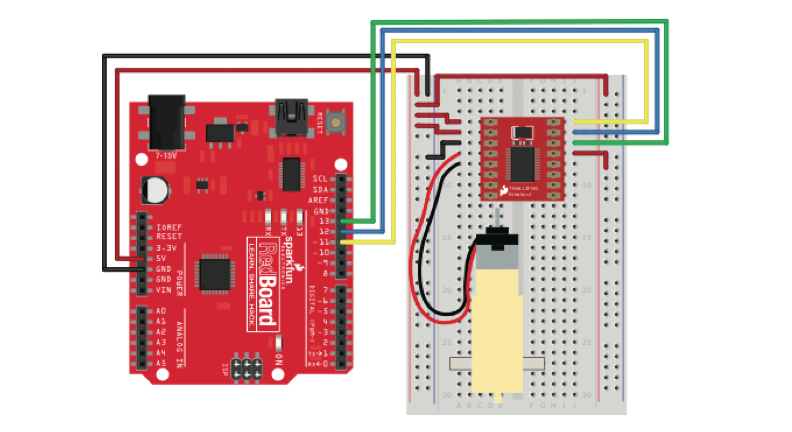
Starting from the top left of the H-bridge, connect 5 V to the top two pins, VM and VCC. VM controls the power for the motors, and VCC controls the power for the chip. Next, use a jumper wire to connect one of the chip’s GND pins to the GND rail of the breadboard. There are three pins available for ground on the H-bridge, as you can see in Figure 8-7, and you can use any of these. Next you’ll connect the motor. The motor has two wires: red and black. The orientation of the wires doesn’t actually matter, but for consistency connect the red wire to the pin labeled A01 and the black wire to pin A02. The remaining pins on the left side are those for controlling the second motor and another GND pin, so leave them for now. The pins on the top right of the H-bridge breakout board are for the signal wire connections for Motor A. The topmost pin, labeled PWMA, controls the motor’s speed. Connect this to pin 11 on the Arduino.
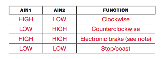
(Remember that pins 3, 5, 6, 9, 10, and 11 all have PWM capability and can be used with the analogWrite() function.) The next two pins, labeled AIN2 and AIN1, are used to control the direction and drive of Motor A, which you can do by setting these pins to different combinations of HIGH and LOW. Table 8-1 shows the combinations. Connect AIN2 to Arduino pin 12 and AIN1 to Arduino pin 11.
Lastly you’ll need to disable the STBY pin. As mentioned earlier, this H-bridge IC has a standby pin that allows you to put the chip into a low-power sleep mode, which is useful for applications where power consumption is a concern. For this project, you don’t need this feature, so you’ll disable it. This chip is designed with STBY as an active low input. This means that when this pin is LOW, it goes into standby mode. To disable standby, you’ll connect this pin directly to 5 V on the power rail.