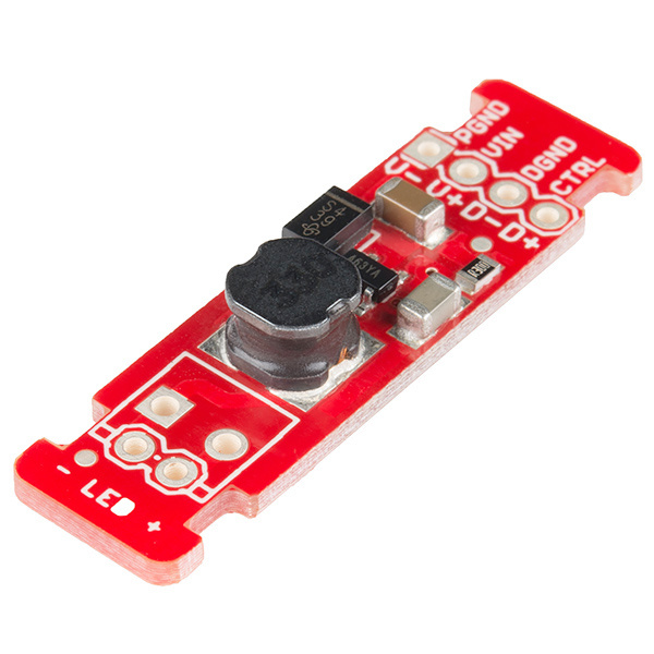
The FemtoBuck is a small-size, single-output constant current LED driver. By default, the FemtoBuck is driven at 350mA. That current can be reduced by either presenting an analog voltage or a PWM signal to the board.
Here are some topics you should know before using the FemtoBuck. Have a look if you need more information.
For the FemtoBuck, we've increased the voltage ratings on the parts to allow the input voltage to cover the full 36V range of the AL8805. Note that the supply voltage must be at least 6.0V, and should be at least 2-3V higher than the forward voltage of the LED(s) to be driven.
Since the FemtoBuck is a constant current driver, the current drawn from the supply will drop as supply voltage rises. In general, efficiency of the FemtoBuck is around 95%, depending on the input voltage.
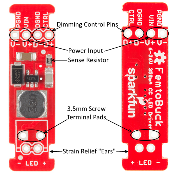
One signal input is provided for dimming control. A ground pin (DGND) is provided to reference against the controlling module for accuracy. Dimming can be done by an analog voltage (20%-100% of max current by varying voltage from .5V-2.5V) or by PWM (so long as PWM minimum voltage is less than .4V and maximum voltage is more than 2.4V) for a full 0-100% range.
Another ground (PGND) pin is available next to the power supply pin to provide a high-current return path. The spacing on the four holes on the input side is 0.1" for standard headers.
The output side has a 0.1" spaced hole pair as well as a 3.5mm spaced hole pair, to allow the user to attach our 3.5mm screw terminals.
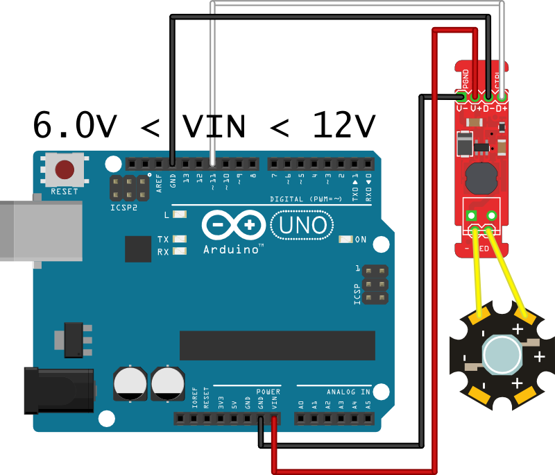
If you have only one or two LEDs, you can connect the FemtoBuck directly to the VIN pin on your Arduino. You will need to power the board from an external supply, as the 5V provided by USB isn't high enough to power the FemtoBuck.
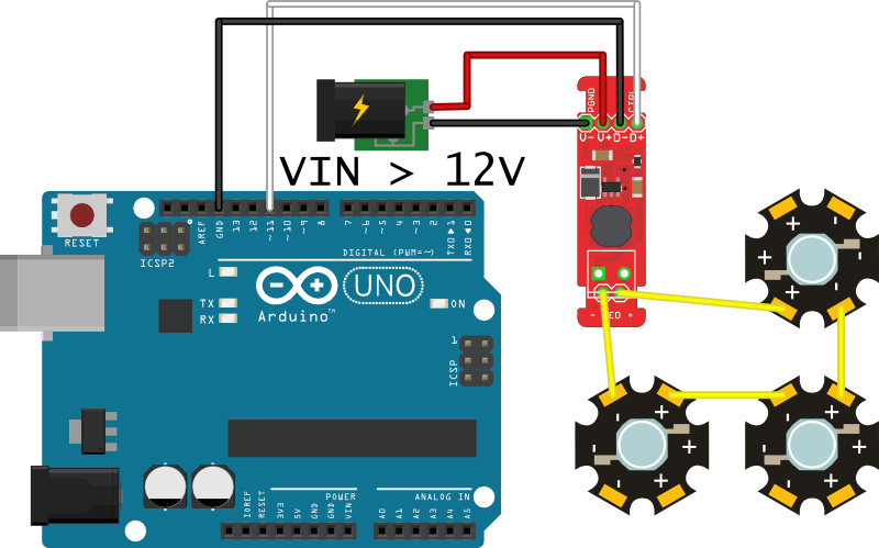
If you have more than a couple of LEDs, you should provide an independent power supply from the Arduino. Multiple LEDs can be connected in series, as shown, and the supply voltage should be at least 2-3V higher than the sum of the forward voltages of the LEDs.
For instance, our blue 3W LEDs have a forward voltage of 3.2V to 3.8V. To be on the safe side, use the highest voltage in the range. If you want to connect three of them, you'd need a power supply of ~14V or greater (3.8V + 3.8V + 3.8V = 11.4V; add 2V of "head room").
Since 14V is greater than the Arduino can tolerate on its input, we have to provide an external supply.
It is possible to increase the maximum current of the FemtoBuck board up to 1A per channel. To do so, replace the current sense resistor with smaller values. To calculate the new value for the resistor, use this formula:
Thus, for a 1A current, you'd want a 0.1Ω resistor. Don't forget to be wary of current ratings; at 1A, the sense resistor will be dissipating 1/10W, so you probably want a resistor of at least 1/8W rating. The package is a standard 0805.
The "ears" on either end of the board allow you to use a zip tie to secure the wires to the board after soldering them down.
Finally, take note of the size of the FemtoBuck. If desired, the entire board can be slid into a piece of 9mm heat shrink tubing to provide insulation and strain relief.
Consider checking out these other tutorials for more information about concepts in this guide:
learn.sparkfun.com | CC BY-SA 3.0 | SparkFun Electronics | Niwot, Colorado