RedStick Hookup Guide
Contributors:
 MTaylor
MTaylor 
Hardware Overview
The following lists the features of the RedStick:
- A boost regulator providing 5V to the Atmega328p from an input range of 2 to 6 volts.
- 16 MHz system clock (allowed because of the additional supply voltage)
- Uno compatible in the Arduino IDE. Simply select the board "Arduino/Genuino Uno" and go!
- USB end matches standard USB thickness and width.
What the RedStick is not:
- A RedBoard -- it doesn't provide 3.3 volts, only 5.
- A battery charger -- The RedStick turns off the battery when plugged into a USB port.
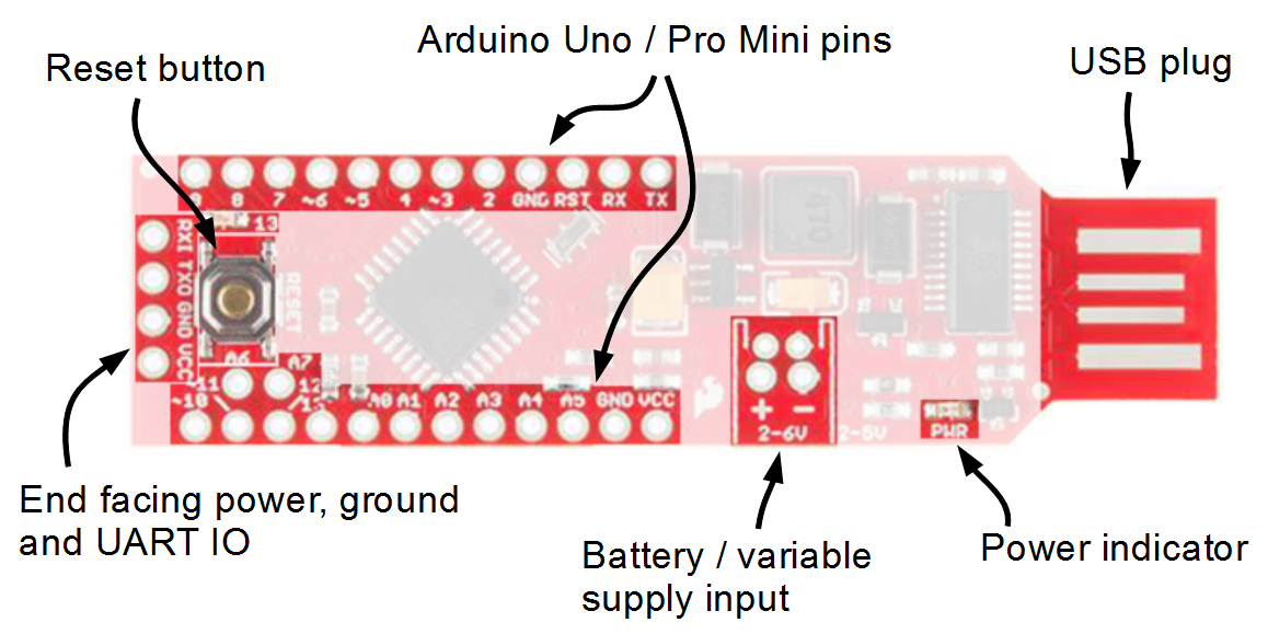
Parts of the RedStick
The following table lists all of the pins on the RedStick and their functionality.
| Pin Silk |
Function | Notes |
|---|---|---|
| TX | Serial transmit |
This is serial data coming out of the RedStick. |
| RX | Serial Receive |
This is serial data coming in |
| 2 | Digital |
|
| ~3 | Digital with PWM |
|
| 4 | Digital | |
| ~5 | Digital with PWM |
|
| ~6 | Digital with PWM |
|
| 7 | Digital | |
| 8 |
Digital | |
| 9 | Digital | |
| ~10 | Digital / PWM / SS |
|
| ~11 |
Digital / PWM / MOSI |
SPI bus |
| 12 | PWM / MISO |
SPI bus |
| 13 | Digital / SCK / LED |
SPI bus |
| A0 | Digital / Analog |
|
| A1 | Digital / Analog |
|
| A2 | Digital / Analog |
|
| A3 |
Digital / Analog |
|
| A4 |
Digital / Analog / SDA |
I2C bus -- some applications require pull-up |
| A5 |
Digital / Analog / SCL |
I2C bus-- some applications require pull-up |
| A6 | Analog |
Analog only! |
| A7 | Analog | Analog only! |
| RXI |
Serial Receive |
Electrically tied to RX |
| TXI | Serial Transmit |
Electrically tied to TX |
| VCC |
Microprocessor Power (Boost output) |
If using as input, supply regulated 5.0 v |
| GND | Ground | |
| + | Battery Positive |
Supply 2.0 to 6.0 volts |
| - | Battery Negative |
This is also GND |