With the power of Raspberry Pi, Python, avrdude, a custom HAT with cable adapter, we developed our own spin on AVR programming that turned out pretty darn robust. In addition to creating a stand alone solution, it was a great experiment to learn more about running a Raspberry Pi "headless", auto-launching python modules on bootup, file management, file parsing, general GPIO control, using the built-in SPI hardware on the Raspberry Pi, and even some logic level conversion.
If you'd like to create your own "headless" AVR programmer, all of the hardware design files and code are hosted on a GitHub here:
The commit history tells a lot of this story, but this tutorial fills in some of the gaps and includes more general information that is helpful outside of our specific application.
Over the past 10+ years, we have used a programmer called the AVR ISP MKII in SparkFun Production. It has served us well, but due to a couple pain points and finally an EOL notice, it was time to upgrade.

At first glance, one might think, "okay, what's the latest programmer from ATMEL? Can't we just swap them out for the old ones?" With our current programming methods, it turned out to be a bit more complicated than that. Also, we do a lot of AVR programming at SparkFun spread across 50+ products, so the problem was actually a pretty big one that needed a reliable and long term solution.
We use batch files a lot in production. If there is an executable GUI that we have to run to program an IC on a product, then we immediately try to find a command line version of that program and automate as much as possible.
With the MKII programmers, our two available options were: Use the GUI (AVR Studio), or do it all in command line. Once you know your commands, then you can put those into a batch file, and a technician can simply double click on a batch file to begin programming - wahoo!! This is how we've done it forever.
(Oldschool Memory Lane Side Note) Well, actually, right as I came on board in 2007, we were manually cutting and pasting the commands from text files into our command line window and reading all of the output to find "Flash verified." Dang, what a pain. I remember thinking, "There's got to be a better way!". Then I went batch file crazy, and three years later did some pretty wonky DIY ganged programming. Look at this beast:
You can also check out the progression of testing methods here:
So all this to say: The problem was bigger than we thought. At the time, each of our programming procedures for AVR chips used a custom batch file that called STK500.exe, that was buried deep within the AVR studio file structure.
After exploring a few available off the shelf products, we quickly fell victim to the classic engineer's curse and thought, "Hey, I could design this better myself!" As it ~~usually~~ always does, this sort of adventure became a long journey.
A stand-alone solution for programming AVR chips has always been a dream of mine. If there was an off the shelf solution (similar to the PICkit3 for PICs), then we probably would have migrated sooner. But there wasn't, so we continued to use the MKIIs. With the day to day stuff and lots of new products coming out, it's tough to make time for these sorts of projects. And so it was this solution (known as the Pi_Grammer around here) that has been a project of mine for almost two years now.
Although, it's not really correct to call it "our own" because it truly builds upon many open source tools that were already available. This is our spin on how to create a stand-alone AVR programmer. So in true open source fashion, here is a tutorial to share what we learned along the way!
Overall, the MKII programmers have done quite well, considering how long and how much we've used them. We are careful with our equipment, but after programming tens of thousands of ICs, you have to expect some wonkiness both in the hardware and the software.
My team and I are known as Quality Control here at SparkFun. One of our responsibilities is to design, build, document, and maintain the testing equipment for production. This not only includes the test jigs that we design, but also includes making sure that their windows desktop machines are working and have up to date (or hacked and working) drivers for all our testing needs.
If production sees any issues at all, they call us up, and we try and solve the issue at that moment. It's usually pretty time sensitive, because we run such a lean ship down in production. Whatever build is held up, is probably going to go out of stock in the next few hours, and so it's very important that we get up and programming immediately!
Back in the day (2008-ish), this was an hourly occurrence. When it was just me as the only QC person in production, I remember production issue response would eat up most of my day. A day with only one issue was considered a good one! Now we probably only see a couple issues a month.
So knowing this, it is clear to see that when any problem happens in production, it causes QC much pain.
The main pain points were as follows:
Drivers - Windows updates conflicting with device drivers. All too often, we'd see the following message pop up on our programming batch files:
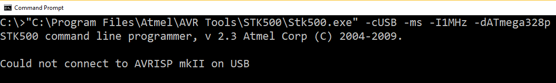
The cause for this was usually the fact that Windows would do an auto update over the weekend, and then a tech comes in on Monday morning to see this failure in their batch file. UGH!
As a side note, the last workaround that allowed us to use MKIIs on Windows 7 was a great little tool called Zadig. I recommend checking it out if you need to force your computer to use the darn driver you exactly want it to:
AVR Studio Versions - New versions of AVR Studio conflicting with older versions. We started using the Atmel ICE for some programming of SAMD21 chips, and that needs the latest AVR Studio 6 or 7 (which comes with a new program called "ATPROGRAM") All our old batch files call "STK500.exe" so that was an issue. It became a dance on each technician's computer as to which version they had installed, in which order they were installed, and which "actual" un-install happened correctly. No fun.
Ribbon Cables Wear and Tear - The ribbon cables failing to make a connection after too many cycles. Ribbon cables work great for 20, 30, 50? cycles, but after so long, those solder-less razor-blade connections get loose and no longer connect.
Internal Servers Down - This last one was pretty rare, but occasionally our internal servers would go down, and the batch files wouldn't run because there was no access to the network hosted hex file.
How do we eliminate all of these problems for good? Make the new solution in-house and completely stand alone! No more auto updates!
My first approach was to use another AVR chip to do the programming. It had been done before by a few others, and documented quite well.
This is what I came across first:
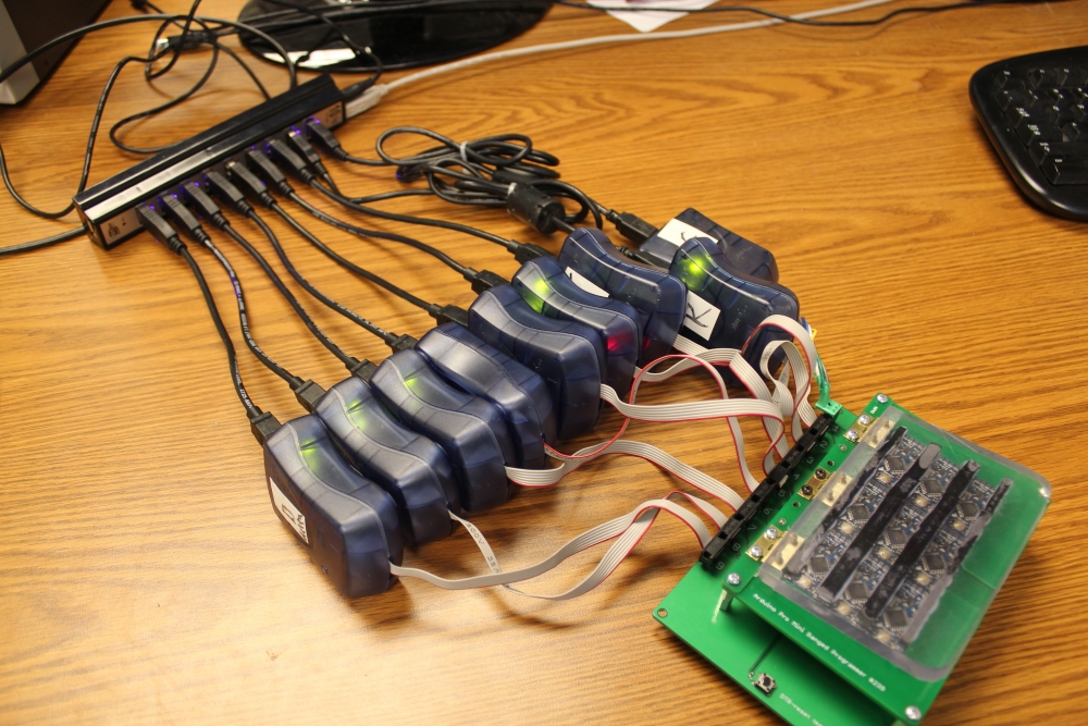
I found that for some of our combined hex files, this wasn't going to fit in the flash. Also, the process to get the hex data into an array and into the compiled code that lives on the programmer was a bit tedious. Either way, I jumped into this rabbit hole, and thought this was going to be the solution for RedBoard Programming. This was the twelve-at-a-time beast that I came up with:
My 12-at-a-time Redboard programming jig is 99% done. I can't wait to send it into the wild tomorrow morning! pic.twitter.com/2BkhlOFp3p
— QCPete (@qcpete) October 14, 2015
Wow, crazy to think that was October 2015. Yikes, time has flown!
After some detailed production yield tracking, we ultimately decided that we still needed to test the boards individually, and so we found that this programmer didn't give us any reductions in labor costs. A bit of a let down, but it also proved that this method of programming was too unreliable. After running a few thousand boards through this thing, we found that boards would often fail at programming on first attempt. Not acceptable for production use. A bit of a bummer, but hey you can't be afraid to fail, and we learned a ton! It was also a great excuse to really try out our Actobotics line of products.
After exploring the chip to chip programming option, and finding that it would not work for our application, we searched for another solution. This time we wondered if a Raspberry Pi might do the trick. A quick search of the internet lead us to a great tutorial by Adafruit that uses GPIO to "bit-bang" programming to AVR chips.
We got this up and running quite quickly. Stoked! Made a custom hat, so we could run this headless, and started migrating some of our kit programming procedures. A little slower than the MKII, but it was completely stand-alone and very reliable - I'm in!
My latest @Raspberry_Pi project: stand-alone AVR programming @sparkfun. 3 live in production. Only 100 more to go :) pic.twitter.com/6ci5N5gcCI
— QCPete (@qcpete) September 6, 2016
Then I found that a second or two longer is actually a lot of labor and production was really not digging this.
Looking on a scope I saw the clock signal flying at 84K. This was leading to some programming times of around 4 or 5 seconds, and then an additional 4-5 seconds to verify. Unfortunately, this was not gonna fly in production and we needed to find a faster solution.
In search of faster solutions, we found another tutorial about using the SPI hardware on the Raspberry Pi.
Cool. This should do the trick. Well, also found that you need to also open up SPI hardware on the Pi. Check out this tutorial below on how to do that. Thanks Byron!
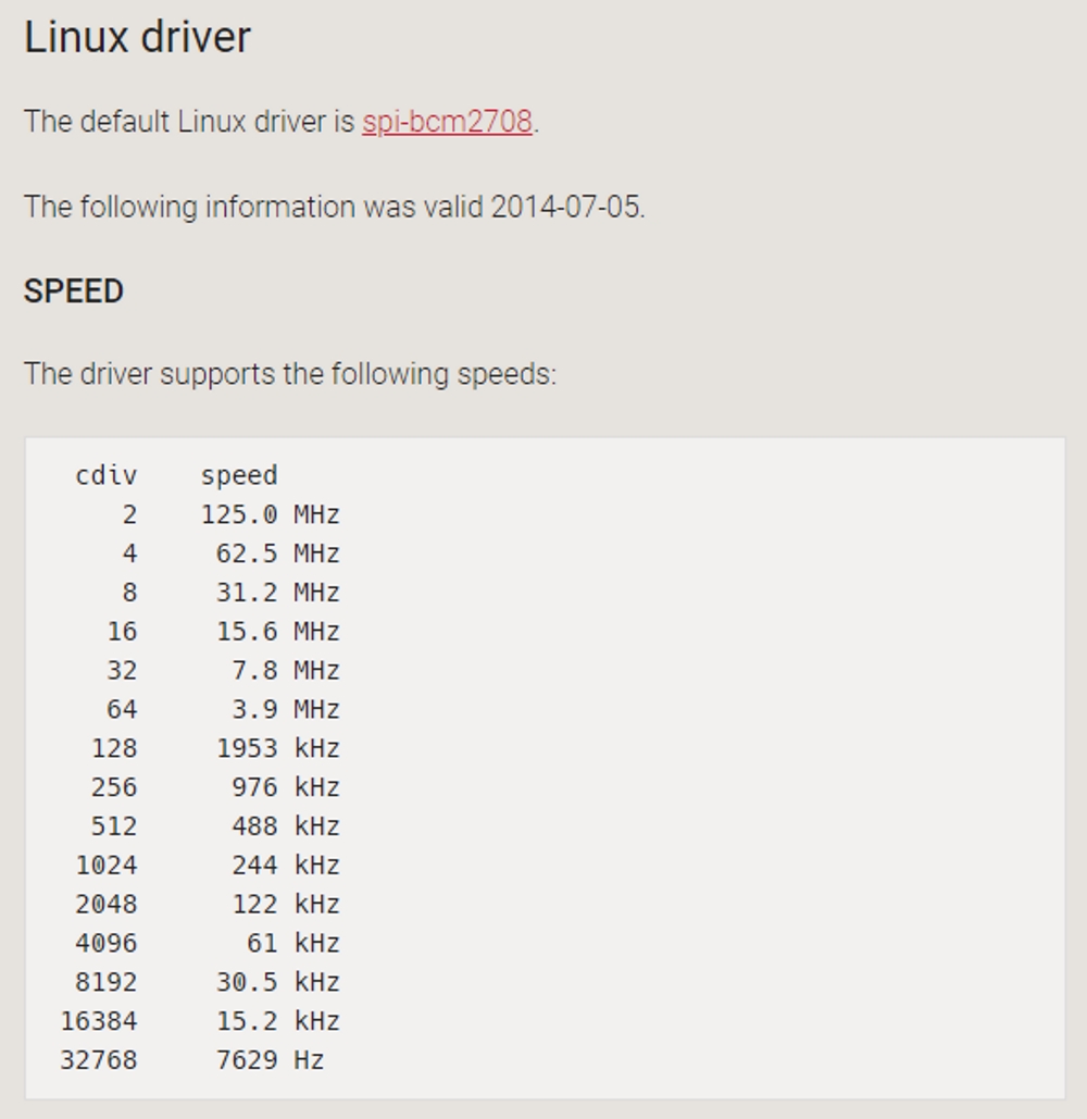
With this new method of programming over the hardware SPI, we were able to get much faster speeds for programming. We really only needed up to 2MHz for most of our chips (less than 1/4 of clock speed is recommended).
After seeing some strange behavior in clock speeds, we found this article explains it well and shows all the available speeds:
A quick modification to rc.local to call Python at bootup means we can run this thing headless. Wahoo!
language:bash
#!/bin/sh -e
# rc.local
# This script is executed at the end of each multiuser runlevel.
# Make sure that the script will "exit 0" on success or any other
# value on error.
# In order to enable or disable this script just change the execution
# bits.
# By default this script does nothing.
# Print the IP address
_IP=$(hostname -I) || true
if [ "$_IP" ]; then
  printf "My IP address is %s\n" "$_IP"
fi
python /home/pi/test.py &
exit 0
Note the most important line here:
language:bash
python /home/pi/test.py &
And don't forget that "&" and the end of the command - that will actually let your pi continue on to bootup and run the OS!
Test.py basically waits to see a "button" pressed to engage programming (pi_program.sh). In this case, it is actually a capsense IC that is sending HIGH/LOW to a GPIO on the pi. To read the entire test.py, you can check it out on the repo here:
And the pi_program.sh file is basically the single call to avrdude to actually do the programming. It looks something like this on most of our production machines:
language:bash
#program flash and lock bits
sudo avrdude -p $DEVICE -C /home/pi/avrdude_gpio.conf -c linuxspi -P /dev/spidev0.0 -b 2000000 -D -v -u -U flash:w:$firmware:i -u -U lock:w:$LOCK:m 2>/home/pi/flash_results.txt
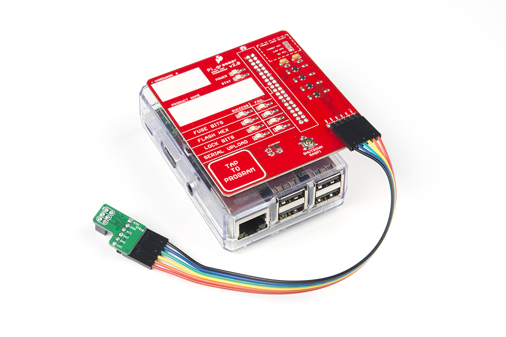
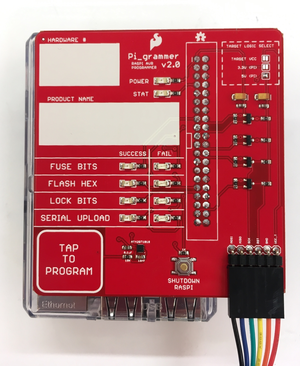
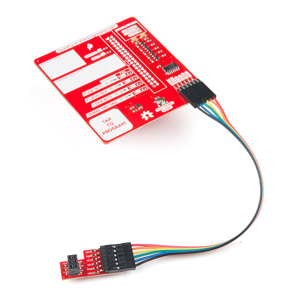
The last ingredient is a custom hat that allows for triggering and LED indicators to the user. Also, added a shutdown button, for goodness sake!
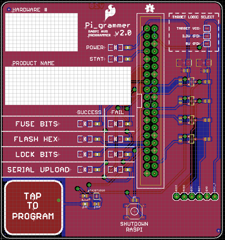
In order to blink those nice new LEDs on the HAT, we'd need the Python module to be able to parse the output from avrdude, and blink the success or fail LED as needed. Oh man, What a dream! Python makes this so easy.
Often times, the readout from a program can be pretty lengthy (with useful information), but when you are programming tons and tons of boards, you just want to see Success or Failure in the readout and not have to look through a ton of text.
This is something that we added into our batch files years ago. Using our old batch files, we've been parsing "tokens" returned from stk500.exe and the code is cryptic. Here's what a typical batch file might look like:
language:bash
FOR /F "tokens=*" %%i IN ('"%step1%"') DO (
if "%%i" == "Fuse bits verified successfully" echo Success at %$step1%
) & (
if "%%i" == "Target voltage is within 5%% of wanted value" (echo Target Voltage Good)
) & (
if "%%i" == "Target voltage is NOT within 5%% of wanted value" (echo %%i) & goto menu
) & (
if "%%i" == "WARNING! One or more operations failed! Please examine the output log above!" (echo Failed at %$step1%) & goto menu
) & (
if "%%i" == "Could not connect to STK500 V2 on USB" (echo %%i) & goto menu
) & (
if "%%i" == "Could not connect to AVRISP mkII on USB" (echo %%i) & goto MENU
)
Oh dang, that's ugly. In Python, I first sent the output to a text file with this command:
language:python
#erase and then write FUSE bits
sudo avrdude -p $DEVICE -C /home/pi/avrdude_gpio.conf -c linuxspi -P /dev/spidev0.0 -b 125000 -D -v -e -u -U hfuse:w:$HIGH_FUSE:m -u -U lfuse:w:$LOW_FUSE:m -u -U efuse:w:$EXT_FUSE:m 2>/home/pi/fuse_results.txt
Notice that little trick using the "2>":
language:python
2>/home/pi/fuse_results.txt
This is actually where all of the output debug from avrdude is getting saved to a text file.
Finally, we can do the parsing of the text file in Python like so:
language:python
f = open('/home/pi/fuse_results.txt', 'r')
    for line in f:
            if 'avrdude: 1 bytes of hfuse verified' in line:
                    print line
                    hfuse = True
            elif 'avrdude: 1 bytes of lfuse verified' in line:
                    print line
                    lfuse = True
            elif 'avrdude: 1 bytes of efuse verified' in line:
                    print line
                    efuse = True
            elif 'avrdude: AVR device not responding' in line:
                    print line
f.close()
So much cleaner! Thank you Python!
To learn more about file handling, here's a great tutorial that got us up and running:
The truly beautiful thing about Python is that anything you want to do is usually a google search away. It's remarkable how much support there is for python tools. Paired with a headless pi and the sky is the limit!
At some point during my research I read that the hardware SPI pins on the Raspberry Pi are never supposed to see a logic level higher than 3.3V. Oops! I've been programming 5V targets all day.
I figured it was better safe than sorry. And isn't the whole point of my design to be reliable? So I messed around with the TXB converter for a while, but couldn't get it to work. I had also tried the bi-direcitonal logic level converter and it just worked, so I decided to go that route. Some nice jumper selections were added to the design to choose where I want the target logic level to come from.
Another thing that came up on this HAT design, was how to properly shut down the Raspberry Pi from the Python module. Ah yes, it was just another Google search away:
language:python
def restart():
    command = "/usr/bin/sudo /sbin/shutdown -r now"
    import subprocess
    process = subprocess.Popen(command.split(), stdout=subprocess.PIPE)
    output = process.communicate()[0]
    print output
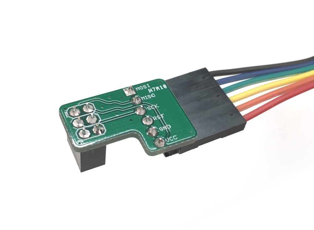
I also decided to go with a custom adapter board. The ribbon cables on the MKIIs were always dying on us, so I wanted to ensure we wouldn't see any of those issues. I went with a 1x6 jumper cable and a custom little adapter board to mate with out standard 2x3 AVR programming header.
This worked out pretty good, but as scope creep settled in, I did revise this once. The V2 had the target VCC come back on the 6th pin, so that could be an option to use in setting the target logic level.
This added feature actually came with a second feature I didn't anticipate. If you jumper both the "target supplied" VCC and one of the Raspberry Pi supplied jumpers (3.3V or 5V), then you can power the target. This was super handy for those programming procedures of bare ICs. Now our techs only have to plug in a single cable for programming and power. Wahoo!
A long time ago we switched from using a mechanical button to engage testing to capsense pads. Even if a mechanical button is rated for 100K cycles, it will probably die before that, and what a pain to have to replace.
On all of our test jigs, we use the capsense library and two I/O pins on the Arduino to "read" a capsense pad. Rather than going this route on the Raspberry Pi, I opted to put a dedicated capsense IC on the HAT and then just read the I/O like a digital pin to engage programming.
This worked great... until... the darn chip when EOL. Eeek!
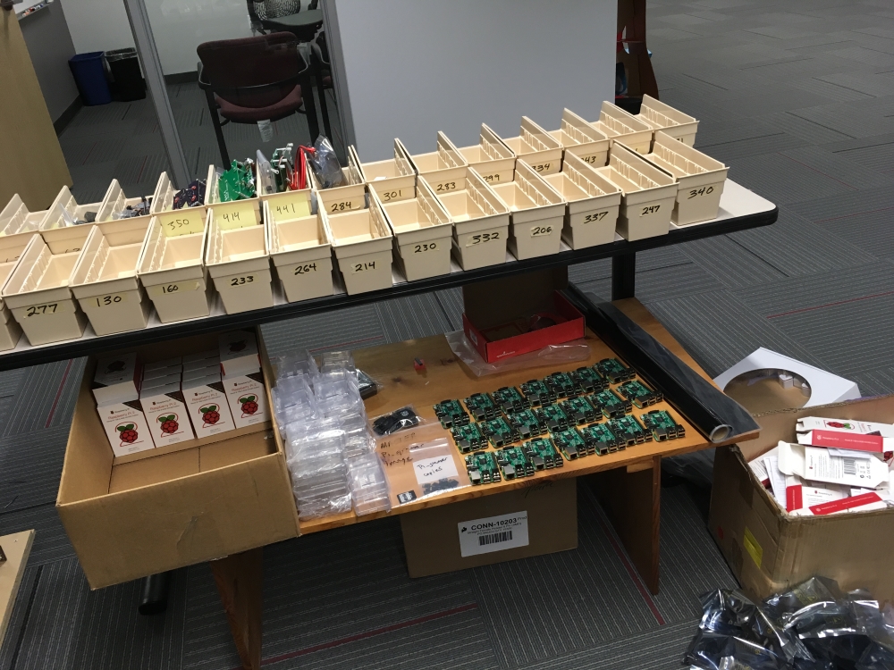
It turned out that it was only the specific package of the capsense IC that went EOL, and that the manufacturer was going to continue to make a smaller QFN version of the chip. So we revised the HAT and all is well. This beautiful bin of HATs arrived on my desk. Thanks production!!
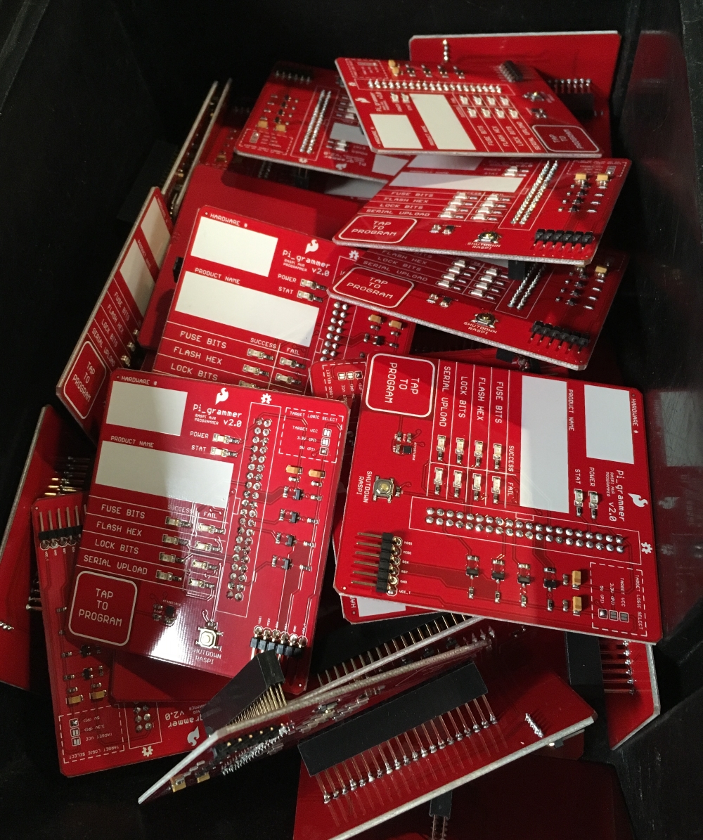
The last step was to slap these HATs on the 60+ Raspberry Pis sitting on my desk and deploy to production!
I had not used a Raspberry Pi for any project before this and wow, was I surprised at how awesome they are! It took me a little while to get used to doing so much work in command line (the file permissions stuff was painful at first), but once I started typing sudo in front of everything, I was up and running! Here are some tips that I would recommend to any newbie to Raspberry Pis. There is so much more so learn, and it's usually only a Google search away. I hope these will come in handy.
Superuser Do -- Use “sudo” in front of every command.
Pi GPIO -- GPIO control/read in python rocks. Check out the tutorial here.
"Batch" Files -- “.sh” files on a Pi are like “.bat” files in MSDOS.
Useful Command -- "sudo killall python" is very handy. "sudo killall avrdude" also! This ended up being a key ingredient for fixing a sneaky little problem that popped up later in production.
Invisible Characters -- Don’t edit files on a windows machine. The darn invisible characters (NL and CF). Grimlens I tell you!! Some really strange behavior happens when these extra invisible characters exist in the pi_program.sh file.
I eventually just committed to editing all files on the Raspberry Pi to avoid these problems. The built-in text editor is pretty nice. One of my staff on the QC team is way into VIM, and can rock some serious shortcuts.
Headless Pis - rc.local is a pretty cool way to launch some stuff on bootup. We call a python module called test.py for all of our programming needs. You could really put any commands in there that you want. We find this really handy because we run these Pi_grammers in production without a monitor, keyboard or mouse - “headless” as they say.
Serial Upload Timeout -- If something is wrong during a serial upload, avrdude can take FOREVER to timeout. This can look like the headless pi is frozen. We eventually fixed this by taking a snapshot of the upload_results.txt file, parsing it, and then calling "sudo killall avrdude" if it looked like it was gonna fail.
** Hardware SPI** -- Opening up SPI lines in raspi-config. Check out the tutorial here.
Keyboard to US English -- Beware, there are oh-so-many windows to click/select through, but eventually you can have a standard English US keyboard if you like. It's in raspi-config.
GPIO Drive/Sink Limitations -- Beware that there are I/O pins that cannot drive/sink an LED. On a my first proto of the HAT, I chose some I/Os that weren't good for LEDs, and had to swap them out. I still don't have a definitive list, but I do know for sure that the 9 GPIOs on the current design work great!
The biggest takeaway we have learned from this epic journey is that we had a dream (super robust, stand-alone production programming), and it was only possible because of the great work done by many other people in the open source community. Cheers and thank you!


Ready to use a Raspberry Pi as a stand-alone programmer? Try checking out the Pi AVR Programmer Hat!
For more information about the Pi_Grammer and , check out the resources below:
Want to check out some other SparkFun production processes or information about burning bootloaders on microcontrollers? Check out some of these related tutorials:
learn.sparkfun.com | CC BY-SA 3.0 | SparkFun Electronics | Niwot, Colorado