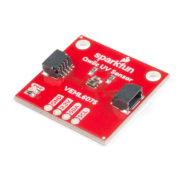
The VEML6075 is SparkFun's latest UV sensing solution. The VEML6075 implements a simple photodiode to measure the levels of UVA (320-400 nm) and UVB (280-320 nm) radiation. We can read the intensity of this light in irradiance, and from there, calculate the UV Index. The Qwiic UV Sensor has two spectrum ranges of measurement, UVA (365 ±10nm), and UVB. (330 ±10nm)
To get started, you'll need a microcontroller to control everything. You may not need everything though depending on what you have. Add it to your cart, read through the guide, and adjust the cart as necessary.
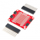
Now to get into the Qwiic ecosystem, the key will be one of the following Qwiic shields to match your preference of microcontroller:
You will also need a Qwiic cable to connect the shield to your UV sensor, choose a length that suits your needs.


If you aren't familiar with the Qwiic system, we recommend reading here for an overview.
| Qwiic Connect System |
We would also recommend taking a look at the following tutorials if you aren't familiar with them.
First let's check out some of the characteristics of the VEML6075 sensor we're dealing with, so we know what to expect out of the board.
| Characteristic | Range |
|---|---|
| Operating Voltage | 1.7V-3.6V |
| Supply Current | 480 µA |
| UVA Resolution | 0.93 counts/µW/cm2 |
| UVA Resolution | 2.1 counts/µW/cm2 |
| I2C Address | 0x10 |
The following table lists all of the VEML6075's pins and the direction of data flow.
| Pin | Description | Direction |
|---|---|---|
| GND | Ground | In |
| 3.3V | Power | In |
| SDA | Data | Bi-directional |
| SCL | Clock | In |
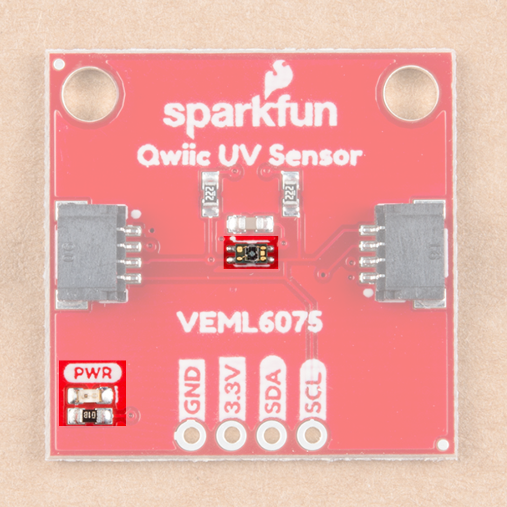
The VEML6075 breakout has pull up resistors attached to the I2C bus; if multiple sensors are connected to the bus with the pull-up resistors enabled, the parallel equivalent resistance will create too strong of a pull-up for the bus to operate correctly. As a general rule of thumb, disable all but one pair of pull-up resistors if multiple devices are connected to the bus. If you need to disconnect the pull up resistors they can be removed by cutting the traces on the corresponding jumpers highlighted below.

The onboard LED (highlighted below) will light up when the board is powered, and the sensor (also highlighted below) should be left uncovered in your application.
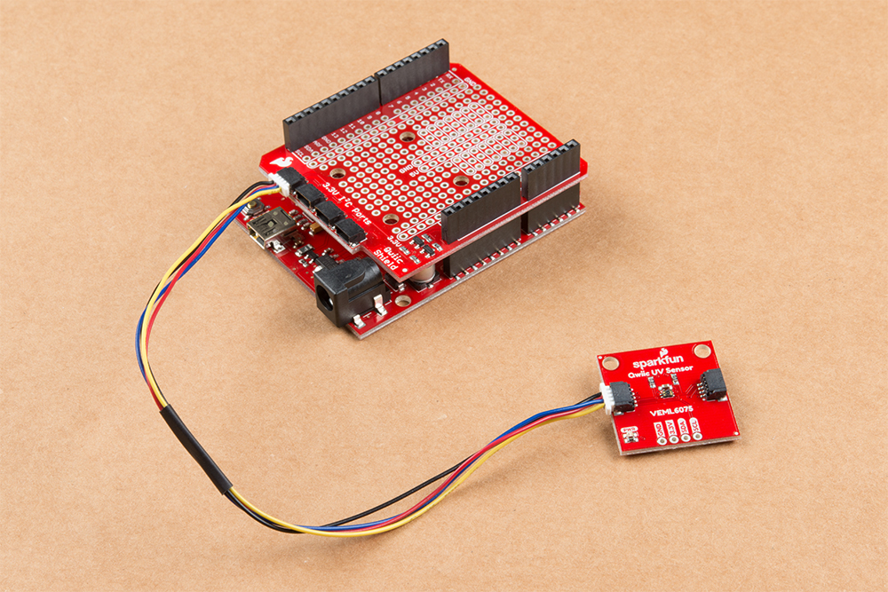
If you haven't yet assembled your Qwiic Shield, now would be the time to head on over to that tutorial. Depending on the microcontroller and shield you've chosen, your assembly may be different, but here's a handy link to the Qwiic Shield for Arduino and Photon Hookup Guide to get you started!
With the shield assembled, SparkFun's new Qwiic environment means that connecting the sensor could not be easier. Just plug one end of the Qwiic cable into the Qwiic UV Sensor, the other into the Qwiic Shield and you'll be ready to upload a sketch and figure out how much sunscreen you need to put on to keep yourself from turning into a lobster. It seems like it's too easy to use, but that's why we made it that way!
Note: This example assumes you are using the latest version of the Arduino IDE on your desktop. If this is your first time using Arduino, please review our tutorial on installing the Arduino IDE. If you have not previously installed an Arduino library, please check out our installation guide.
First, you'll need the SparkFun VEML6075 Arduino library. You can obtain these libraries through the Arduino Library Manager. Search for Sparkfun VEML6075 Arduino Library to install the latest version. If you prefer downloading the library from the GitHub repository and manually installing it, you can grab them here:
Before we get started developing a sketch, let's look at a pertinent enum, VEML6075_error_t. Many of our functions will return this data type as a way of pointing out errors. The enum is shown below, notice how negative numbers are returned for errors, while a 1 is returned for a success.
language:c
typedef enum {
    VEML6075_ERROR_READ            = -4,
    VEML6075_ERROR_WRITE           = -3,
    VEML6075_ERROR_INVALID_ADDRESS = -2,
    VEML6075_ERROR_UNDEFINED       = -1,
    VEML6075_ERROR_SUCCESS         = 1
} VEML6075_error_t;
boolean begin(void) --- Returns true if the VEML6075 is attached properly.
VEML6075_error_t begin(TwoWire &wirePort) --- Give begin() a TwoWire port to specify the I2C port
void setDebugStream(Stream &debugPort = Serial) --- Enables debug statements, defaults to Serial for output
boolean isConnected(void) --- Returns true if the VEML6075 is attached properly.
VEML6075_error_t setIntegrationTime(veml6075_uv_it_t it) --- Set integration time for a measurement to 50, 100, 200, 400, or 800 ms. The options for the veml6075_uv_it_t enum are shown below.
IT_50MS,
IT_50MSIT_100MSIT_200MSIT_400MSIT_800MSIT_RESERVED_0IT_RESERVED_1IT_RESERVED_2IT_INVALID
veml6075_uv_it_t getIntegrationTime(void) --- Returns the current integration time
VEML6075_error_t setHighDynamic(veml6075_hd_t hd) --- Changes to high dynamic mode by passing in DYNAMIC_HIGH and normal dynamic mode by passing in DYNAMIC_NORMAL. High dynamic mode increases the resolution by a factor of 2.
veml6075_hd_t getHighDynamic(void) --- Returns the current high dynamic setting.
VEML6075_error_t setTrigger(veml6075_uv_trig_t trig) --- Set's trigger to continuos read (NO_TRIGGER) or (TRIGGER_ONE_OR_UV_TRIG)
veml6075_uv_trig_t getTrigger(void) --- Returns current trigger mode as NO_TRIGGER, TRIGGER_ONE_OR_UV_TRIG or TRIGGER_INVALID.
VEML6075_error_t trigger(void) --- Triggers once.
VEML6075_error_t setAutoForce(veml6075_af_t af) --- With auto force enabled, the UV sensor will conduct one measurement whenever the host writes TRIGGER_ONE_OR_UV_TRIG to setTrigger(), otherwise, the VEML6075 continuously takes measurements. Passing in AF_DISABLE or AF_ENABLE will disable and enable the auto force mode.
veml6075_af_t getAutoForce(void) --- Returns the current auto force setting as AF_DISABLE, AF_ENABLE, or AF_INVALID
VEML6075_error_t powerOn(boolean enable = true) --- Powers the VEML6075 on from shutdown mode.
VEML6075_error_t shutdown(boolean shutdown = true) --- Puts the VEML6075 in shutdown mode (800 nA)
uint16_t rawUva(void) --- Reads raw UVA data
uint16_t rawUvb(void) --- Reads raw UVB data
float uva(void) --- Returns UVA data, adjusted with values from the UV compensation registers.
float uvb(void) --- Returns UVA data, adjusted with values from the UV compensation registers.
float index(void) --- Returns the UV index.
float a(void) --- Returns UVA data, adjusted with values from the UV compensation registers.
float b(void) --- Returns UVA data, adjusted with values from the UV compensation registers.
float i(void) --- Returns the UV index.
uint16_t uvComp1(void) --- Gets value for UV compensation
uint16_t uvComp2(void) --- Gets value for UV compensation
uint16_t visibleCompensation(void) --- Gets value for visible compensation
uint16_t irCompensation(void) --- Gets value for IR compensation
VEML6075_error_t deviceID(uint8_t * id) --- Prints device ID on debug stream.
VEML6075_error_t deviceAddress(uint8_t * address) --- Prints device address on debug stream.
Now that we have our library installed and we understand the basic functions, let's run some examples for our UV sensor to see how it behaves.
To get started with the first example, open up File > Examples > Examples from Custom Libraries > SparkFun VEML6075 UV Sensor > Example1_Stream_UV. In this example, we begin by creating a VEML6075 object called uv and then initializing our sensor object in the setup() loop. The code to do this is shown below.
language:c
VEML6075 uv; // Create a VEML6075 object
void setup() {
Serial.begin(115200);
Wire.begin();
// the VEML6075's begin function can take no parameters
// It will return true on success or false on failure to communicate
if (uv.begin() == false) {
Serial.println("Unable to communicate with VEML6075.");
while (1) ;
}
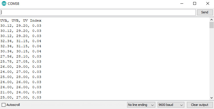
Serial.println("UVA, UVB, UV Index");
}
Once we've initialized our sensor, we can start grabbing measurements from it. We pull the UVA and UVB values as well as the index using uv.uva, uv.uvb and uv.index The void loop() function that does this is shown below.
language:c
void loop() {
// Use the uva, uvb, and index functions to read calibrated UVA and UVB values and a
// calculated UV index value between 0-11.
Serial.println(String(uv.uva()) + ", " + String(uv.uvb()) + ", " + String(uv.index()));
delay(250);
}
Opening your serial monitor to a baud rate of 9600 should show the calibrated UVA and UVB levels as well as the current UV index
To get started with the second example, open up File > Examples > Examples from Custom Libraries > SparkFun VEML6075 UV Sensor > Example2_Configure_UV. In this example, we begin by creating and initializing a VEML6075 object called uv. We then change the integration time (the amount of time over which a measurement is taken) and change to high dynamic mode (which increases the resolution) using the following lines of code (contained in the setup() loop)
language:c
void setup() {
  Serial.begin(115200);

  Wire.begin();

  // The begin function can take a TwoWire port as a parameter -- in case your platform has more than
  // the one standard "Wire" port.
  // begin will return VEML6075_SUCCESS on success, otherwise it will return an error code.
  if (uv.begin(Wire) != VEML6075_SUCCESS) {
    Serial.println("Unable to communicate with VEML6075.");
    while (1) ;
  }

  // Integration time: The VEML6075 features five selectable integration times. This is the amount of
  // time the sensor takes to sample UVA/UVB values, before integrating the readings into averages.
  // Valid integration times are:
  //      VEML6075::IT_50MS -- 50ms
  //      VEML6075::IT_100MS -- 100ms
  //      VEML6075::IT_200MS -- 200ms
  //      VEML6075::IT_400MS -- 400ms
  //      VEML6075::IT_800MS -- 800ms
  // The library defaults integration time to 100ms. (Set on every call to begin().)
  uv.setIntegrationTime(VEML6075::IT_200MS);

  // High dynamnic: The VEML6075 can either be set to normal dynamic or high dynamic mode.
  // In high dynamic mode, the resolution is increased by about a factor of two.
  // Valid dynamic settings are:
  //      VEML6075::DYNAMIC_NORMAL -- Normal dynamic mode
  //      VEML6075::DYNAMIC_HIGH -- High dynamic mode
  // The library defaults the dynamic to normal
  uv.setHighDynamic(VEML6075::DYNAMIC_HIGH);
}
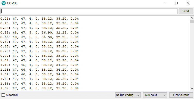
Now that we've changed around a few of our UV sensors settings, we will read the raw UVA and UVB values along with their compensation values from visible and infrared noise, which are used to calculate the values we obtain from uv.uva and uv.uvb. The below code reads both raw values as well as calibrated values.
language:c
void loop() {
  // In addition to uva, uvb, and index, the library also supports reading the raw
  // 16-bit unsigned UVA and UVB values, and visible-light and infrared compensation values with
  // the functions rawUva, rawUvb, visibleCompensation, and irCompensation. These values,
  // in addition to pre-calculated scalars, are used to generate the calculated UVA, UVB and index values.
  Serial.println(String((float)millis() / 1000.0) + ": " +
                 String(uv.rawUva()) + ", " + String(uv.rawUvb()) + ", " +
                 String(uv.visibleCompensation()) + ", " + String(uv.irCompensation()) + ", " +
                 String(uv.uva()) + ", " + String(uv.uvb()) + ", " + String(uv.index()));
  delay(100);
}
Opening your serial monitor to a baud rate of 9600 will show both raw values as well as calibrated values in the order of Time, raw UVA, raw UVB, visible compensation, IR compensation, calculated UVA, calculated UVB, calculated UV Index.
To get started with the third example, open up File > Examples > Examples from Custom Libraries > SparkFun VEML6075 UV Sensor > Example3_Shutdown. In this example, we'll go over how to put the sensor into low power shutdown mode. We begin by creating and initializing a VEML6075 object called uv. We initialize the object in setup the exact same way as the first example. We then loop through, reading our calibrated UVA and UVB values. Every 50 reads, we switch the power state of the UV sensor. When we put the VEML6075 in shutdown mode, it only draws 800 nA of current while ignoring any reads we attempt to throw at it. The code that handles this is shown below.
language:c
const unsigned int READINGS_BETWEEN_SHUTDOWN = 50;

void loop() {
  static unsigned int numReadings = 1;
  static boolean powerOnState = true;

  if ((numReadings % READINGS_BETWEEN_SHUTDOWN) == 0) {
    if (powerOnState) {
      // Use shutdown to disable sensor readings. The sensor will consume less power in this state.
      uv.shutdown();
      Serial.println("Shut down");
      powerOnState = false;
    } else {
      // Use powerOn to enable sensor readings.
      uv.powerOn();
      Serial.println("Power up!");
      powerOnState = true;
    }
  }
  Serial.println(String((float)millis() / 1000.0) + ": " + String(uv.uva()) + ", " + String(uv.uvb()) + ", " + String(uv.index()));
  numReadings++;

  delay(200);
}
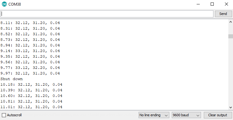
The part in our serial output where we shut the VEML6075 down is shown below. notice how after the sensor goes into shutdown mode, we always pull the exact same reading from it. This is because it is not longer updating those registers.
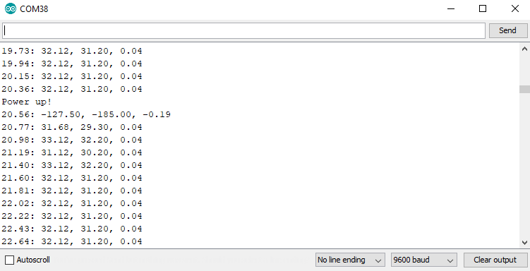
After 50 more readings, the UV sensor powers back on and starts taking readings. This process looks like the image below in serial. Notice how the first reading after we turn the sensor back on is garbage.
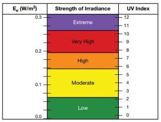
In this example we will go through the steps of calculating the UV Index from our raw UVA and UVB values, which the library does for you. However, it's always good to take a bit of a deeper dive into these things. To begin, go ahead and open up File > Examples > Examples from Custom Libraries > SparkFun VEML6075 UV Sensor > Example4_Calculate_UVI. The UV index can be calculated based on the average irradiance of our UVA and UVB light. This irradiance has a linear relation to our UV index, check out the chart below from the VEML6075 Application Guide to see the relationship between irradiance and UV index.
The VEML6075 is based around a silicon photodiode, which is susceptible to not only UV, but also visible light and wavelengths as low as infrared. This generates undesirable noise in our UV signal, so we factor in values from visible (uv.visibleCompensation()) and infrared (uv.irCompensation()) noise compensation registers. To get a little more accuracy out of this signal, you'll have to calibrate it against the golden sample under a solar simulator like a Newport LCS-100, using a calibrated UVI meter such as a Davis 6490 UVI sensor changing the values of the below constants, located at lines 32-35.
language:c
const float CALIBRATION_ALPHA_VIS = 1.0; // UVA / UVAgolden
const float CALIBRATION_BETA_VIS  = 1.0; // UVB / UVBgolden
const float CALIBRATION_GAMMA_IR  = 1.0; // UVcomp1 / UVcomp1golden
const float CALIBRATION_DELTA_IR  = 1.0; // UVcomp2 / UVcomp2golden
The numerator in each of these constants will be the value from your VEML6075 UV sensor, while the denominator will be the value from the Davis UVI sensor. For example, if you were to change the value of α you would divide the UVA measurement from the VEML6075 by the UVA measurement from the Davis 6490. Setting these constants to 1.0 essentially eliminates this calibration. In 90% of cases, this "golden sample" calibration won't be used, but if you do use it, make sure you calibrate your values once the Qwiic UV Sensor has been placed into it's final enclosure.
The main calibration occurs by adjusting the values of the visible and infrared noise compensation we obtain from the UV sensor. The application manual gives us values for the coefficients, shown in lines 47-50.
language:c
const float UVA_VIS_COEF_A = 2.22; // a
const float UVA_IR_COEF_B  = 1.33; // b
const float UVB_VIS_COEF_C = 2.95; // c
const float UVB_IR_COEF_D  = 1.75; // d
The responsivity converts the raw 16-bit data from the chip into something in units of W/m2. Changing the dynamic and integration time will change the responsivity of the sensor, so be careful changing these values, as you'll have to change the responsivity on lines 41-42.
language:c
const float UVA_RESPONSIVITY = 0.00110; // UVAresponsivity
const float UVB_RESPONSIVITY = 0.00125; // UVBresponsivity
After we have all of these constants set up, we initialize our UV sensor like we normally do, then begin reading values from our sensor and doing the necessary math to convert our irradiance values into UV indices. The code in the void loop() that accomplishes this is shown below.
language:c
void loop() {
  uint16_t rawA, rawB, visibleComp, irComp;
  float uviaCalc, uvibCalc, uvia, uvib, uvi;

  // Read raw and compensation data from the sensor
  rawA = uv.rawUva();
  rawB = uv.rawUvb();
  visibleComp = uv.visibleCompensation();
  irComp = uv.irCompensation();

  // Calculate the simple UVIA and UVIB. These are used to calculate the UVI signal.
  uviaCalc = (float)rawA - ((UVA_VIS_COEF_A * CALIBRATION_ALPHA_VIS * visibleComp) / CALIBRATION_GAMMA_IR)
                  - ((UVA_IR_COEF_B  * CALIBRATION_ALPHA_VIS * irComp) /  CALIBRATION_DELTA_IR);
  uvibCalc = (float)rawB - ((UVB_VIS_COEF_C * CALIBRATION_BETA_VIS * visibleComp) / CALIBRATION_GAMMA_IR)
                  - ((UVB_IR_COEF_D  * CALIBRATION_BETA_VIS * irComp) /  CALIBRATION_DELTA_IR);

  // Convert raw UVIA and UVIB to values scaled by the sensor responsivity
  uvia = uviaCalc * (1.0 / CALIBRATION_ALPHA_VIS) * UVA_RESPONSIVITY;
  uvib = uvibCalc * (1.0 / CALIBRATION_BETA_VIS) * UVB_RESPONSIVITY;

  // Use UVIA and UVIB to calculate the average UVI:
  uvi = (uvia + uvib) / 2.0;

  Serial.println(String(uviaCalc) + ", " + String(uvibCalc) + ", " + String(uvi));
  delay(250);
}
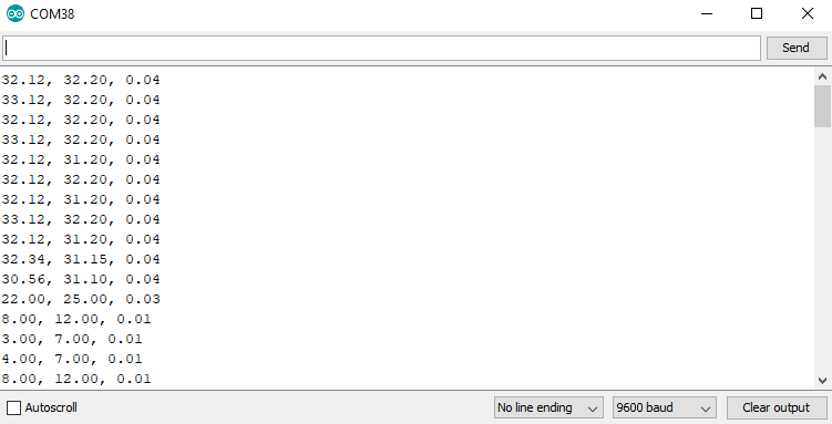
The serial output of this example (at a baud rate of 9600) should look something like the image below.
Now that you've successfully got your Qwiic VEML6075 UV Sensor up and running, it's time to incorporate it into your own project! For more information, check out the resources below:
Need some inspiration for your next project? Check out some of these related tutorials:
learn.sparkfun.com | CC BY-SA 3.0 | SparkFun Electronics | Niwot, Colorado