Qwiic OpenLog Hookup Guide
 Nate,
Nate,  Toni_K, Ell C,
  Englandsaurus
Hardware Overview
Power
The Qwiic OpenLog runs at the following settings:
| VCC Input | 3.3V |
|---|---|
| SDA | 3.3V |
| SCL | 3.3V |
| Idle Current Draw | ~2mA-6mA |
| Active Writing Current Draw | ~20-23mA (dep on microSD card) |
The Qwiic OpenLog's current draw is about 20mA to 23mA when writing to a microSD. Depending on the size of the microSD card and its manufacturer, the active current draw can vary when the OpenLog is writing to the memory card.
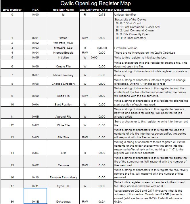
Register Map
The Qwiic Open Log implements a register map type set up if you'd like to create your own library.
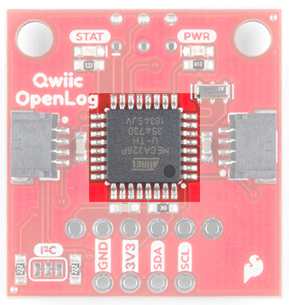
Microcontroller
Like its predecessor, the Qwiic OpenLog runs off of an onboard ATmega328, running at 16MHz thanks to the onboard crystal. The ATmega328 has the Optiboot bootloader loaded on it, which allows the OpenLog to be compatible with the "SparkFun Redboard" board setting in the Arduino IDE.
Interface
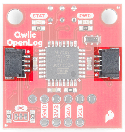
Qwiic Connectors
The primary interface with the Qwiic OpenLog are the Qwiic connectors on either side of the board. If you aren't familiar with the Qwiic system, you are in for a treat! The Qwiic system utilizes I2C protocol to allow multiple “slave” digital integrated circuits (“chips”) to communicate with one or more “master” chips with a mere two wires. Check out all the benefits of the Qwiic System here.
FTDI Header Pins
While the Qwiic OpenLog retains the broken out FTDI header pins, they pins are used specifically for reprogramming the firmware. All logging communication happens through the Qwiic lines and associated broken out pins.
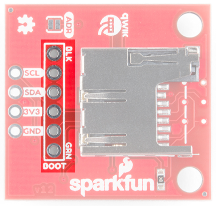
SPI
There are also six SPI test points broken out on the opposite side of the board. You can also use these to reprogram the bootloader on the ATmega328.
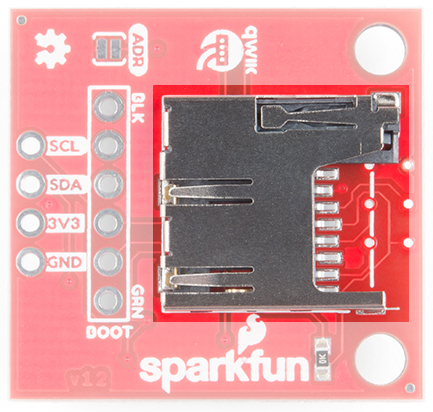
microSD Card
The final interface for communicating with the Qwiic OpenLog is the microSD card itself. To communicate, the microSD card requires SPI pins. Not only is this where the data is stored by the OpenLog, but you can also update the OpenLog's configuration via the config.txt file on the microSD card.
All data logged by the OpenLog is stored on the microSD card. The OpenLog works with microSD cards that involve the following features:
- 64MB to 32GB
- FAT16 or FAT32
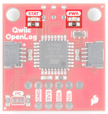
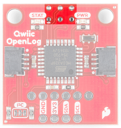
Status LED
There are two LEDs on the OpenLog to help you with troubleshooting.
- STAT - This green LED is connected to Arduino D13 (Serial Clock Line/ ATmega328 PB5). This LED only blinks when the SPI interface is active. You will see it flash when the OpenLog records data to the microSD card.
- PWR - This red indicator LED is attached to Arduino D5 (ATmega328 PD5) and lights when the board is active and functioning.