This guide provides users with functional descriptions, configuration options for the QuickLogic Thing Plus EOS S3. It also serves as a “Getting Started” and “How To” guide.
To follow along with this tutorial, you will need the following materials. You may not need everything though depending on what you have. Add it to your cart, read through the guide, and adjust the cart as necessary.
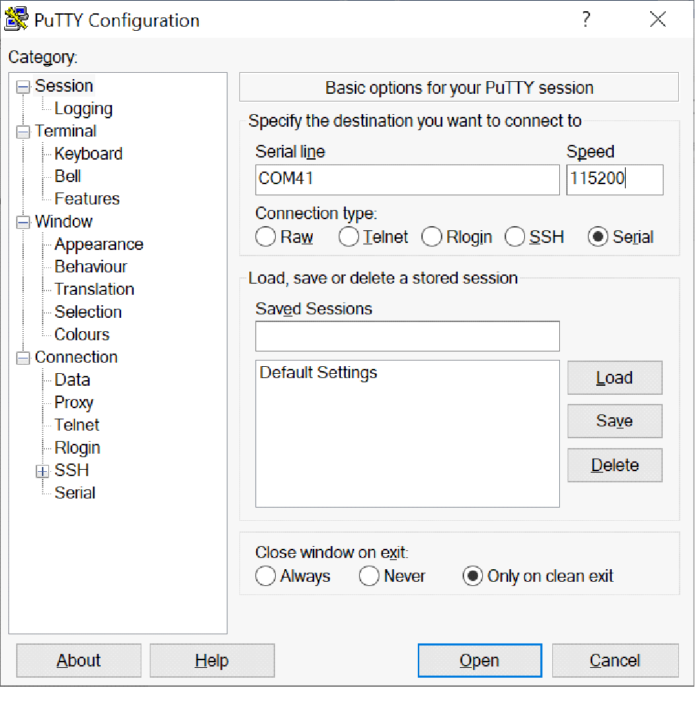
You will also need a computer with a terminal program or any UART console application. For the scope of this tutorial, we will use PuTTY.
If you aren't familiar with the Qwiic system, we recommend reading here for an overview .
 |
| Qwiic Connect System |
If you aren’t familiar with the following concepts, we also recommend checking out a few of these tutorials before continuing.
The QuickLogic Thing Plus EOS S3 is a small form factor system ideal for enabling the next generation of low-power Machine Learning (ML) capable Internet of Things (IoT) devices. Unlike other development boards which are based on proprietary hardware and software tools, the QuickLogic Things Plus is based on 100% open source hardware, compatible with the Feather form factor, and is built around 100% open source software (including the Symbiflow FPGA Tools).
The QuickLogic is powered by QuickLogic’s EOS™ S3, the first eFPGA-enabled Arm Cortex©-M4F MCU to be fully supported with Zephyr RTOS and FreeRTOS.
Other functionality includes:
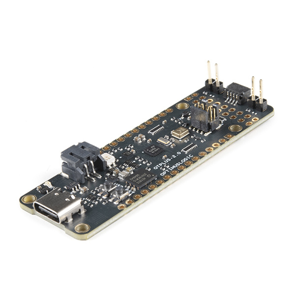
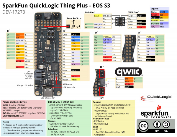
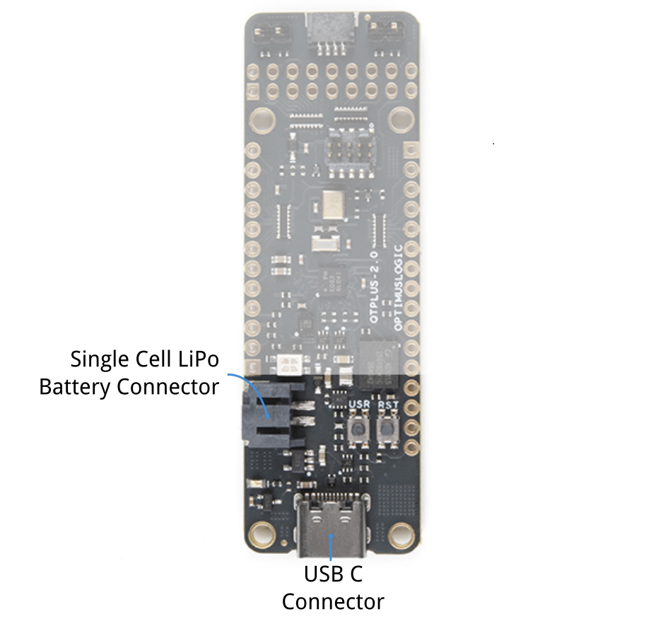
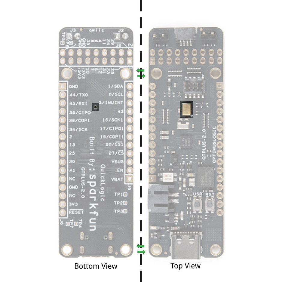
Below is a quick overview of the board layout and components.
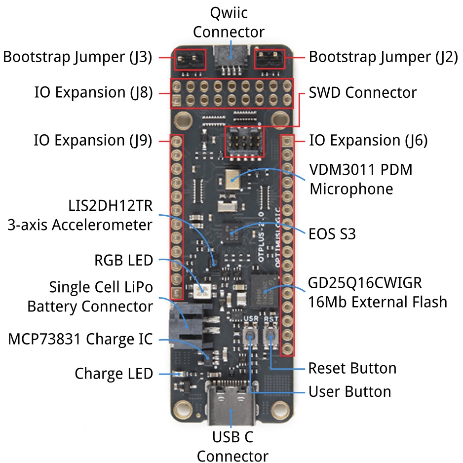
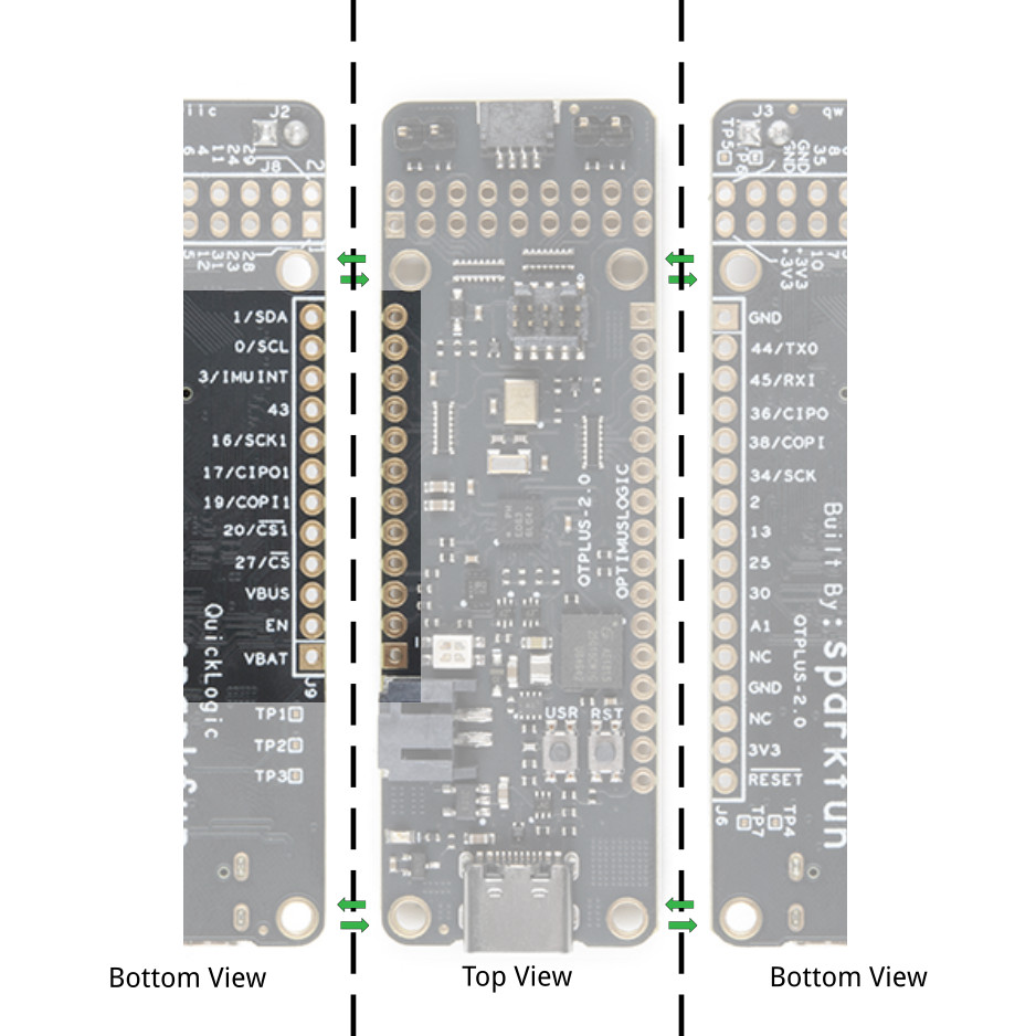
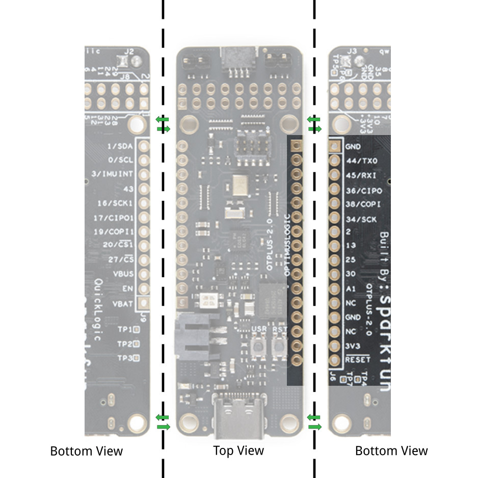
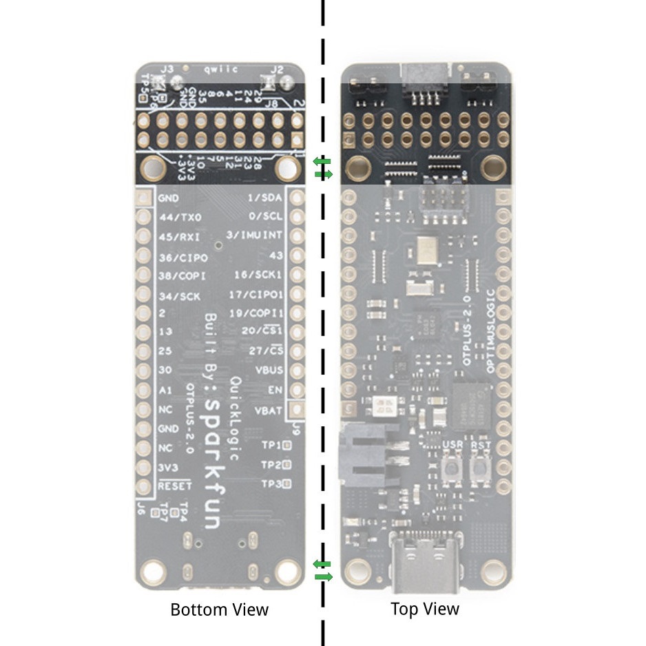
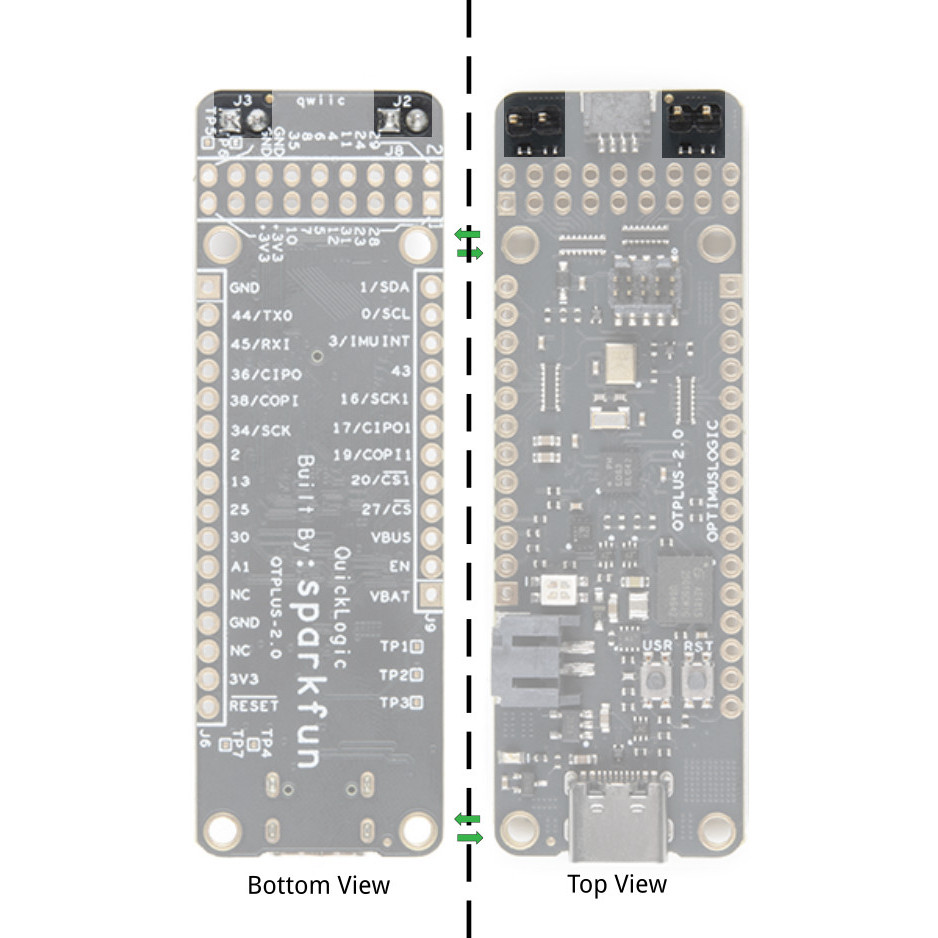
Below is the graphical datasheet of the QuickLogic Thing Plus EOS S3 to reference the pins followed by a table listing the EOS S3 pins. Due to the size of the board and components, the silkscreen is printed on the back of the board. You can flip over the board reference the pin name and its respective function as well.
| EOS S3 MCU IO | QuickLogic Thing Plus Function | Additional Function | Expansion |
|---|---|---|---|
| IO_0 | I2C0 SCL | J9.11 | |
| IO_1 | I2C0 SDA | J9.12 | |
| IO_2 | IO | J6.7 | |
| IO_3 | Accelerometer LIS2DH12TR Interrupt | J9.10 | |
| IO_4 | IO | J8.8 | |
| IO_5 | IO | J8.9 | |
| IO_6 | User Button Input | J8.10 | |
| IO_7 | IO | J8.11 | |
| IO_8 | IO | J8.12 | |
| IO_10 | IO | J8.13 | |
| IO_11 | IO | J8.6 | |
| IO_12 | IO | J8.7 | |
| IO_13 | IO | J6.8 | |
| IO_14 | Serial Wire Debug CLK | J6.4 | |
| IO_15 | Serial Wire Debug DATA | J6.2 | |
| IO_16 | IO | SPI Peripheral CLK | J9.8 |
| IO_17 | IO | SPI Peripheral CIPO (input) | J9.7 |
| IO_18 | Blue LED | N/A | |
| IO_19 | IO | SPI Peripheral COPI | J9.6 |
| IO_20 | IO | SPI Peripheral CSn | J9.5 |
| IO_21 | Green LED | N/A | |
| IO_22 | Red LED | N/A | |
| IO_23 | IO | I2S Peripheral WCLK (Frame) | J8.3 |
| IO_24 | IO | I2S Peripheral DATA (dout) | J8.4 |
| IO_25 | IO | J6.9 | |
| IO_27 | IO | SPI Controller CS2 | J9.2 |
| IO_28 | PDM Data; to isolate, remove R28 | J8.1 | |
| IO_29 | PDM CKO | J8.2 | |
| IO_30 | IO | J6.10 | |
| IO_31 | IO | I2S Peripheral CLK (input) | J8.5 |
| IO_32 | IO | J9.3 | |
| IO_33 | IO | J9.4 | |
| IO_34 | SPI Controller CLK | J6.6 | |
| IO_36 | SPI Controller CIPO | J6.4 | |
| IO_38 | SPI Controller COPI (flash) | J6.5 | |
| IO_40 | IO | N/A | |
| IO_43 | IO | Interrupt Output to Host | J9.9 |
| IO_44 | IO | UART TX | J6.2 |
| IO_45 | IO | UART RX | J6.3 |
| J2 | EOS S3 MCU IO | BGA Pin# | Function |
|---|---|---|---|
| 1 | VBAT | ||
| 2 | 3.3V Circuit Enable | ||
| 3 | VBUS | ||
| 4 | IO_27 | HS | IO; SPI Controller CSn2 |
| 5 | IO_20 | G8 | SPI Peripheral SSn input; EOS S3 boot-strap |
| 6 | IO_19 | H8 | SPi Peripheral COPI input; EOS S3 boot-strap |
| 7 | IO_17 | D7 | SPI Peripheral CIPO output |
| 8 | IO_16 | E7 | SPI Peripheral CLK input |
| 9 | IO_43 | D1 | EOS S3 Interrupt Output |
| 10 | IO_3 | A2 | Accel Interrupt input |
| 11 | IO_0 | B1 | I2C0 SCL |
| 12 | IO_1 | C1 | I2C0 SDA |
| J6 | EOS S3 MCU IO | BGA Pin# | Function |
|---|---|---|---|
| 1 | Ground | ||
| 2 | IO_44 | E1 | S3 UART TX |
| 3 | IO_45 | G1 | S3 UART RX |
| 4 | IO_36 | H3 | SPI Controller CIPO input |
| 5 | IO_38 | E2 | SPI Controller COPI output |
| 6 | IO_34 | F3 | SPI Controller CLK output |
| 7 | IO_2 | A1 | IO |
| 8 | IO_13 | D6 | IO |
| 9 | IO_25 | F7 | IO |
| 10 | IO_30 | F4 | IO |
| 11 | ADC1 | C7 | ADC1 input |
| 12 | No Connect | ||
| 13 | Ground | ||
| 14 | No Connect | ||
| 15 | +3.3V | ||
| 16 | SYS_RSTn | F8 | EOS S3 HW reset input |
| J8 | EOS S3 MCU IO | BGA Pin# | Function |
|---|---|---|---|
| 1 | IO_28 | G5 | PDM microphone Data |
| 2 | IO_29 | F5 | PDM microphone CLK |
| 3 | IO_23 | H6 | I2S Peripheral WCLK Input |
| 4 | IO_24 | G6 | I2S Peripheral DATA output |
| 5 | IO_31 | G4 | I2S Peripheral CLK input |
| 6 | IO_11 | C5 | IO |
| 7 | IO_12 | B5 | IO |
| 8 | IO_4 | B2 | IO |
| 9 | IO_5 | C3 | IO |
| 10 | IO_6 | B3 | User button input |
| 11 | IO_7 | A3 | IO |
| 12 | IO_8 | C4 | IO |
| 13 | IO_10 | A4 | IO |
| 14 | IO_35 | F2 | IO |
| 15 | +3.3V | ||
| 16 | Ground | ||
| 17 | +3.3V | ||
| 18 | Ground |
Below is the SWD connector used to program the board. Taken from the graphical datasheet are the pin labels on the right for reference.
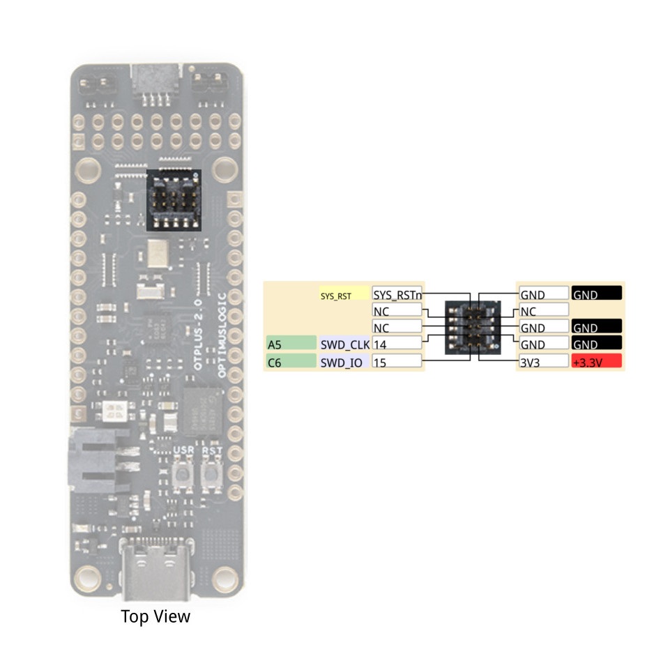
| J7 | EOS S3 MCU IO | Function |
|---|---|---|
| 1 | +3.3V | |
| 2 | IO_15 | SWD_IO |
| 3 | Ground | |
| 4 | IO_14 | SWD_CLK |
| 5 | Ground | |
| 6 | No Connect | |
| 7 | No Connect | |
| 8 | No Connect | |
| 9 | Ground | |
| 10 | SYS_RSTn | Hardware Reset |
There are two pair of IO pins that are reserved for flashing the EOS S3 with a programmer. When booting a program from flash, you'll need to keep these pins open.
There are two ways to provide power to the QuickLogic Thing Plus: USB connector (J5) or Battery connector (J4). When both ports are connected at the same time, the USB power activates the battery charging circuit that provide charging current to the battery.
When using a rechargeable battery, the minimum input voltage will determine the maximum currents that the system needs to support. This is important when connecting additional peripherals to the QuickLogic Thing Plus that also requires connection to +3.3V for supplies.
The MCP73831 LiPo charger is set to ~212.76mA for the default charge rate. Before you plug a battery into the charger, you should be aware of your battery's capacity and the charge current supplied by the charger. To be safe, you should keep the charge current at or below 1C of your battery. That means you should connect a LiPo battery that has a capacity of ~212.75mAh or higher to charge safely. For more information on the charge LED's status, check out the LiPo USB Charger breakout board for the MCP73831.
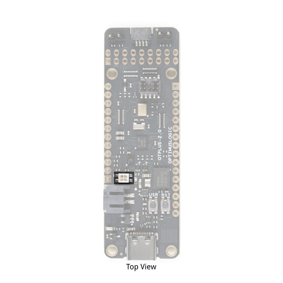
Speaking of LEDs, the board includes a build in RGB LED. As listed earlier in the tutorial, the leds can be controlled using pin 22 (red),p in 21 (green), and pin 18 (blue). Note that the pins are not routed to the edge of the board.
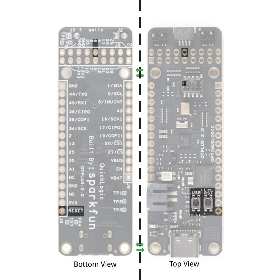
The board includes a user button and hardware reset button. These are also connected to the edge of the board as well. The reset pin is also connected to the SWD pin when connecting to a programmer.
QuickLogic Thing Plus supports direct connection to FeatherWing module (providing that the FeatherWing module has Stack Headers installed) via expansion connector J2 and J3. Refer to AdaFruit's web site for additional information on available FeatherWing modules.
QuickLogic Thing Plus board supports connecting to sensor module with I2C peripheral interface via expansion connectors J2. You can also access the pins along the J9 header.
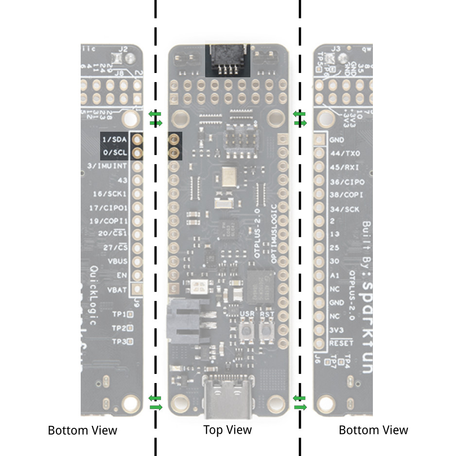
QuickLogic Thing Plus I2C supports I2C Standard mode (100KHz) and Fast mode (400KHz). There is one I2C bus available; additional I2C IP can be implemented in EOS S3 FPGA.
Steps to connect external I2C sensors to QuickLogic Thing Plus board:
Note: You may need to use oscilloscope to validate the rise time for SCL and SDA to stay within rise time specification
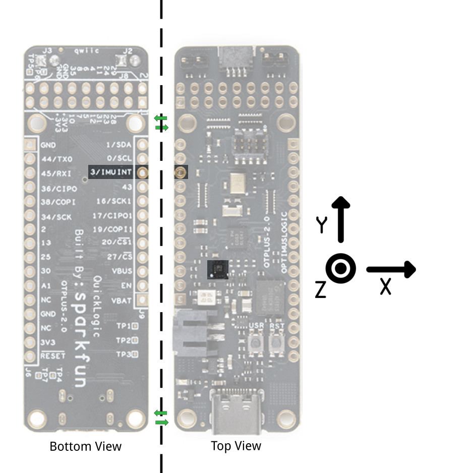
The board includes the LIS2DH12TR triple axis accelerometer. Below is the reference axis of the IC based on the datasheet. This sensor connected to the I2C bus. The address for the accelerometer is set to 0b0011000 (0x18). The accelerometer INT1 pin is connected to pin 3.
QuickLogic Thing Plus board supports connecting to sensor module with SPI peripheral interface via expansion connectors J6 and J9: SPI CONTROLLER CLK (J6 pin 6), SPI CONTROLLER CIPO (J6 pin 4), SPI CONTROLLER COPI (J6 pin 5) and SPI CONTROLLER CS2 (J9 pin 4).

The maximum supported SPI clock frequency is 10MHz.
Steps to connect external SPI sensor to QuickLogic Thing Plus board:
The on-board PDM microphone (Vesper VM3011) is configured as left channel output (driving active data on falling edge of PDM CLK). Based on the design of the microphone, there is a drill hit through the board that allows an opening for the sound.
QuickLogic Thing Plus supports external PDM microphone connection via expansion connector J8: PDM CLK (J8 pin 2) and PDM DATA (J8 pin 1).
Steps to connect one external PDM microphone to QuickLogic Thing Plus board:
To support two external PDM microphones configuration, it is required to disable the connection of the on-board PDM microphone.
QuickLogic Thing Plus supports external PDM microphone connection via expansion connector J8: PDM CLK (J8 pin 2) and PDM DATA (J8 pin 1).
Steps to connect two external PDM microphones to QuickLogic Thing Plus board:

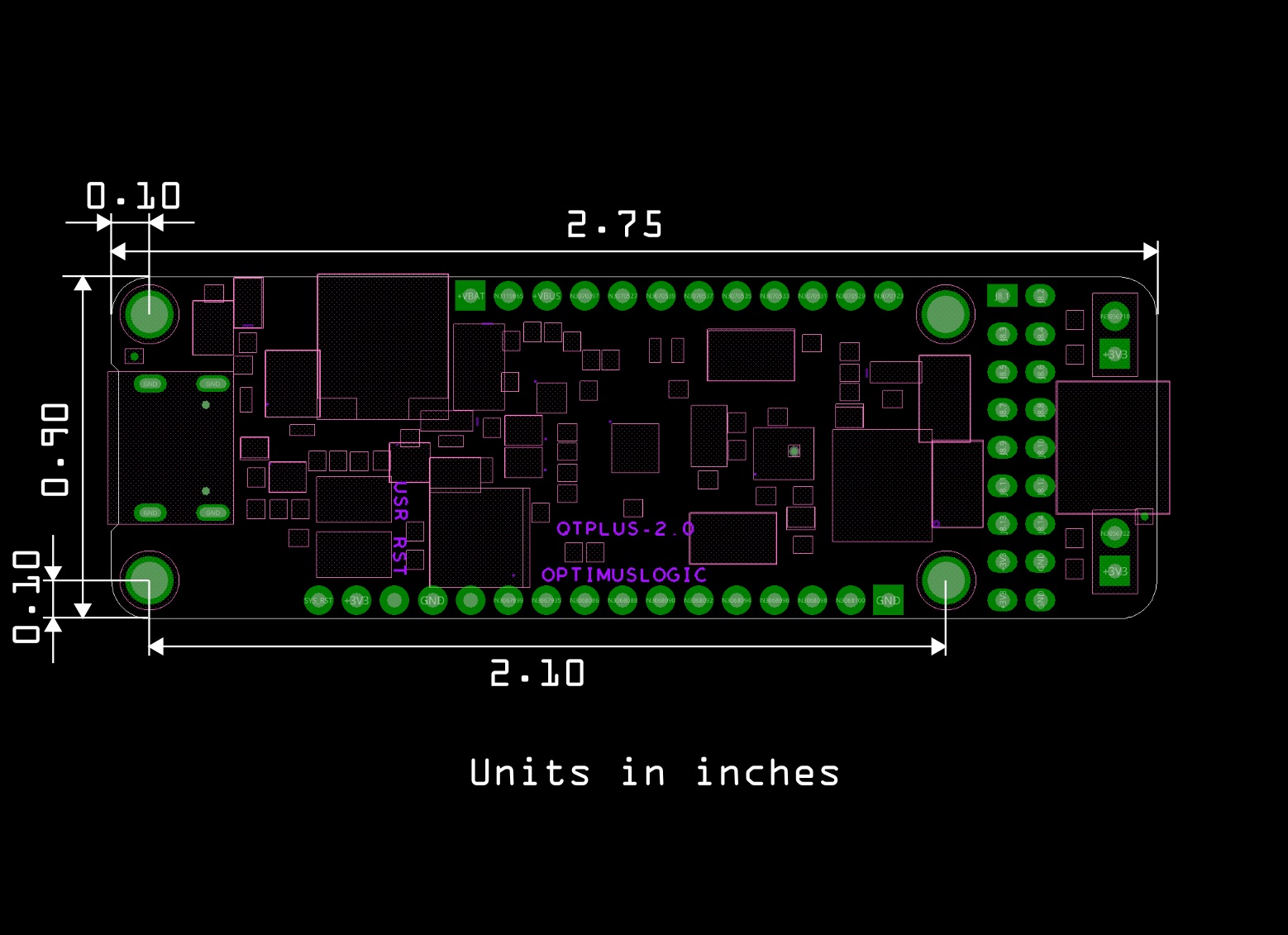
The board is 2.75"x2.10". While the board uses the Thing Plus footprint, length of the board is slightly longer than other Thing Plus designs.
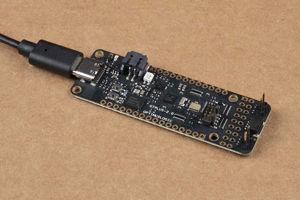
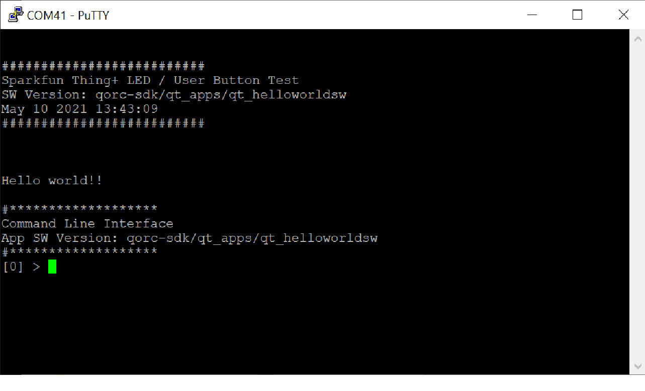
To power and output serial data to terminal window, you will need to insert a USB cable to the board.
The purpose of the pre-loaded program is to make it very fast and straightforward for a new user to verify the board is functioning correctly. While we do production testing on every QuickLogic Thing Plus before we ship, sometimes things happen during shipping or storage. Running this test takes less than a minute to do, requires no knowledge of the QuickLogic Thing Plus, and will give you peace of mind the QuickLogic Thing Plus is ready for you to start innovating freely.
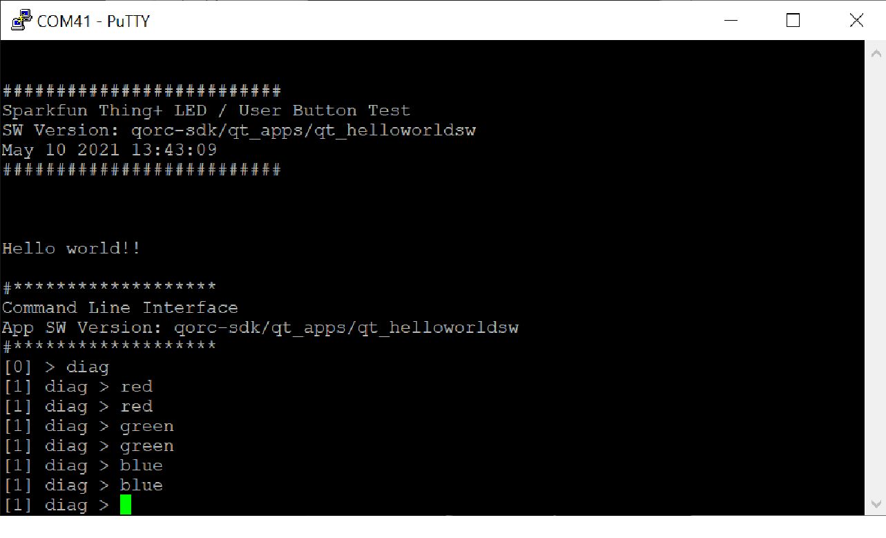
8. Perform the followings in the PuTTY terminal:
a) Type: “diag” to bring up QuickLogic Thing Plus diagnostic menu
b) Type: “help” to bring up the menu of commands
c.) Type: “red”; the command shows red color for LED
d.) Type: “red”; the LED turns off the LED
e.) Try “green” and “blue” command
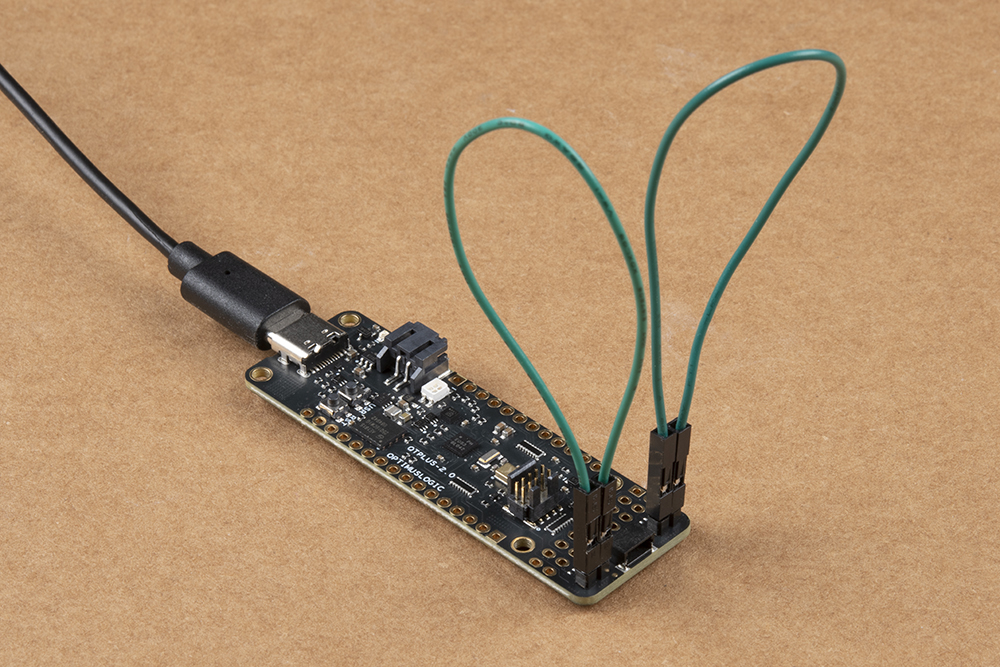
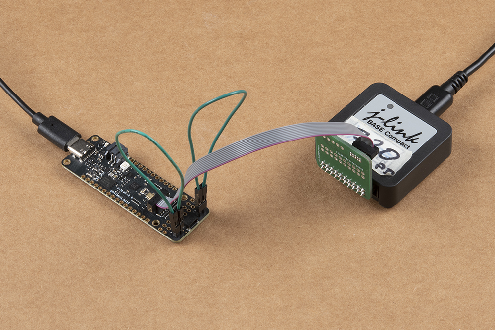
QuickLogic Thing Plus supports loading and testing stand-alone eFPGA design or eFPGA + M4 MCU design, using SWD standard tool such as Segger’s Jlink SWD or OCD. Below are the instructions for system with Windows 10 OS with Segger Jlink pod.
Note:
Note:
Now that you've successfully got your QuickLogic EOS S3 Thing Plus up and running, it's time to incorporate it into your own project! For more information, check out the resources below:
Need some inspiration for your next project? Check out some of these related tutorials:
learn.sparkfun.com | CC BY-SA 3.0 | SparkFun Electronics | Niwot, Colorado