QRD1114 Optical Detector Hookup Guide
QRD1114 Overview
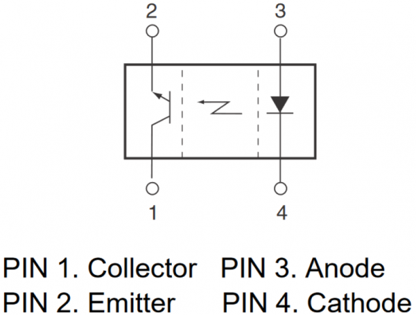
The QRD1114 is a 4-pin device. Two legs break out the infrared LED, and the other two legs break out the collector and emitter pins of the phototransistor (the "base" of the phototransistor is controlled by the IR light returned). The image below, from the datasheet, shows which pin is which.
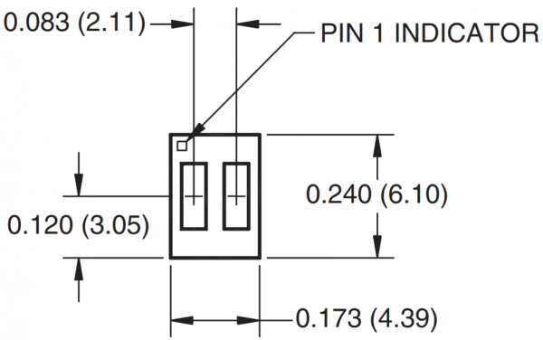
Pin 1, the collector of the transistor, can be found by locating the dot on the top of the component. You should also be able to see two noticeably different-colored rectangles -- one black and one clear. The black rectangle is the phototransistor (the black part is actually a filter cover), and the clear half is the LED.
Looking from the top down, the pins increment in counter-clockwise order. Pin 2 -- the transistor's emitter -- is adjacent to pin 1 along the long side of the body. Pin 3, the LED anode is across the short side of the photodetector from pin 2. And the cathode pin 4 is next to pin 3 and across the body from pin 1.
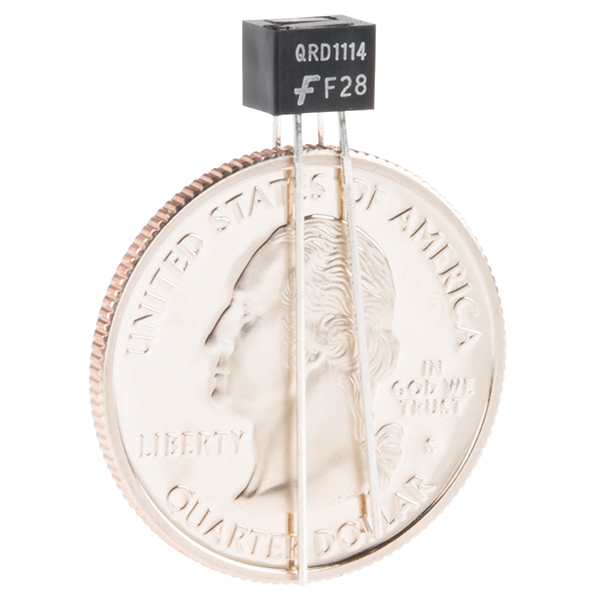
The length of the legs can also help determine which pin is which. Pins 1 and 3 are longer than the other pins; (probably) not coincidentally, these are the "positive" pins of their respective components (collector and anode).
Sensor Characteristics
The QRD1114's infrared LED is just like any other LED you may have used in the past. The forward voltage is typically between 1.2V and 1.7V, which means you'll need at least that much potential on your supply to power the LED. 3.3V or 5V supplies can work just fine, as long as you have a current-limiting resistor.
The LED's maximum forward current is 50mA; more than that has a chance of permanently damaging the part. It's best to aim at delivering around 20mA to the diode.
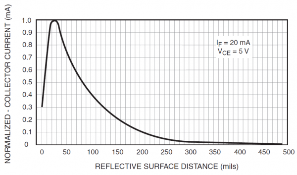
One of the most interesting graphs in the QRD1114 datasheet is this distance versus transistor collector current curve:
The graph above makes assumptions (LED intensity, power to the across the transistor, reflecting material), but it's still a good gauge for estimating a distance based on the output signal. It at least demonstrates a few things about the sensor:
- The output tops out at about 30 mils (0.03", 0.76mm).
- From the peak, it slopes down exponentially.
- At about 125 mil (0.125", 3.18mm), the output signal is already 30% of the peak.
- At about 300 mil (0.3", 7.62mm), changes in the signal become nearly indistinguishable.
- If an object gets too close to the sensor, it will enter a dead zone. Anything closer than about 30 mils (0.03", 0.76mm) is difficult for the detector to see.
TLDR: these sensor's don't have a very large range. They're designed for close proximity sensing. They can reliably detect distances ranging from 0.03 to about 0.4 inches (0.75-10.15mm).


