Programming an FPGA
Blink an LED
Let’s now put all this together into a demo project that will blink an LED.

Create a New Project
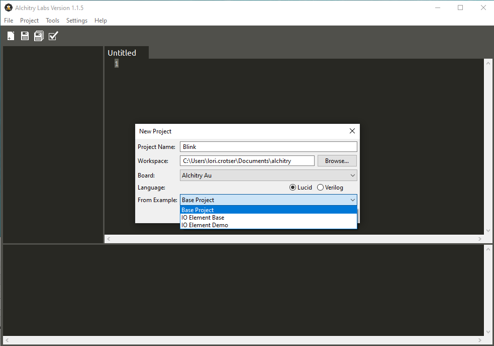
Create a new project in Alchitry Labs and choose Base Project in the From Example dropdown.
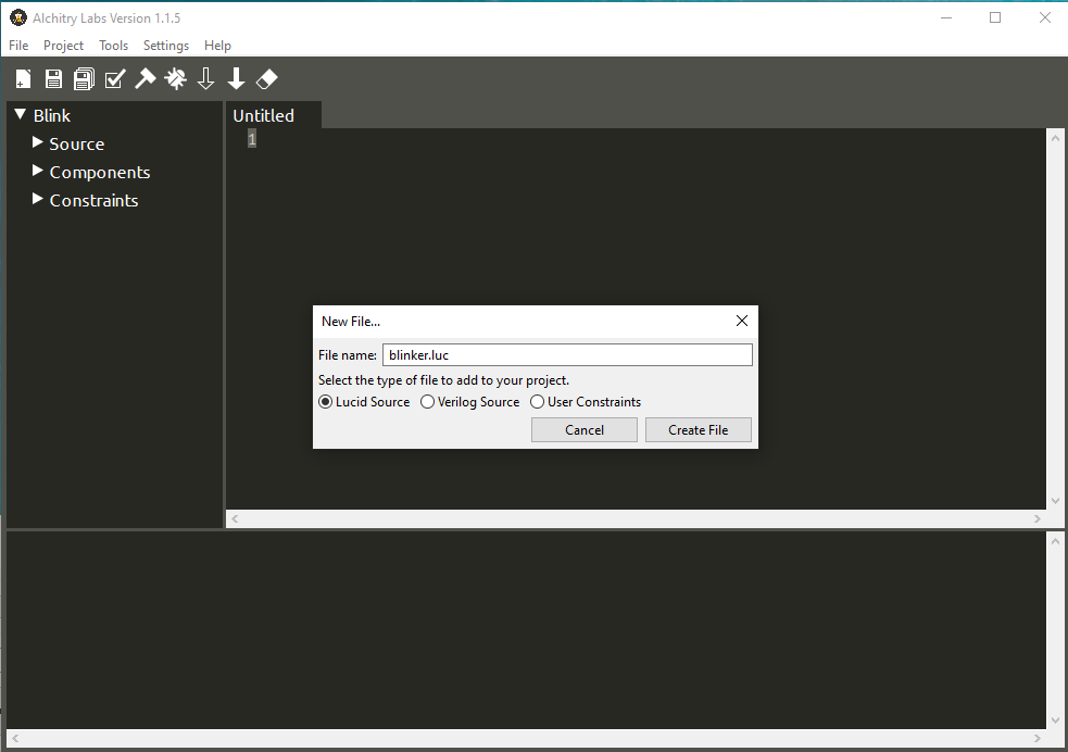
Click the new file icon in the toolbar (leftmost icon) and create a new Lucid Source file named blinker.luc.
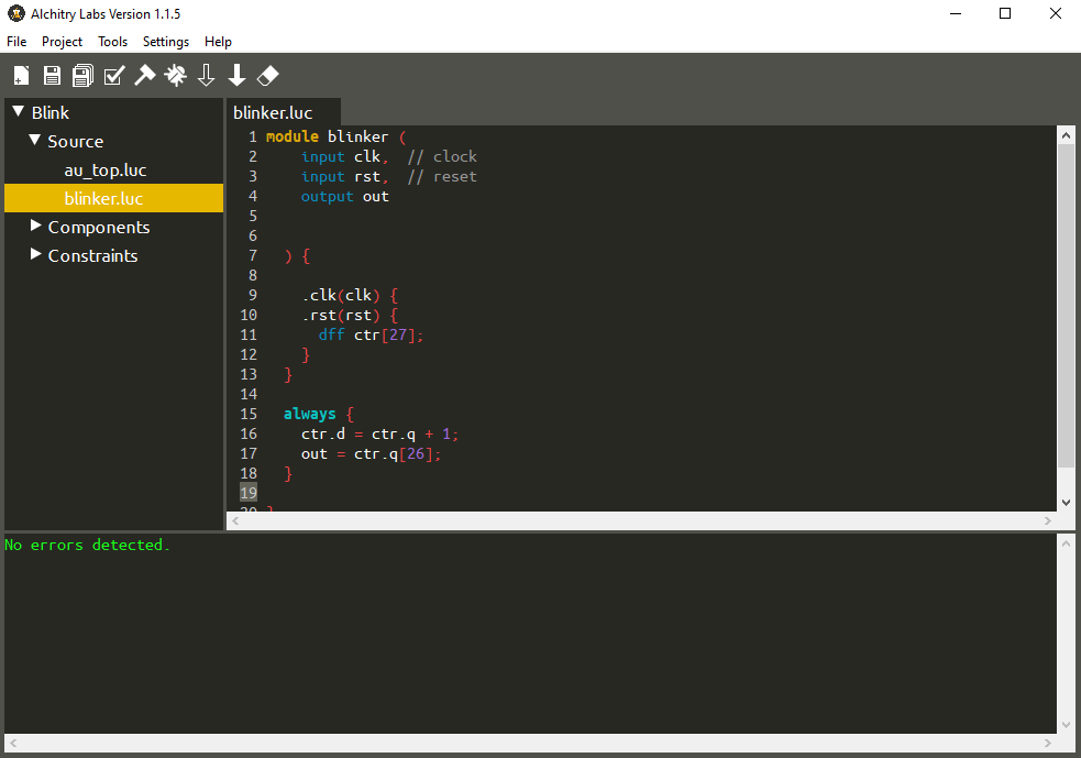
This will create a basic module that looks like the following:
module blinker (
    input clk,  // clock
    input rst,  // reset
    output out
  ) {

  always {
    out = 0;
  }
}
The default module template adds the clock and reset inputs and an output that currently does nothing.
To blink an LED we need to create a counter that will be used to toggle the LED. If we simply toggle the LED each clock cycle it will blink way too fast to be able to see.
We can set up the connection blocks for the clock and reset to make it easier then declare the DFF inside them.
  .clk(clk) {
    .rst(rst) {
      dff ctr[27];
    }
  }
This creates an array of 27 DFFs named ctr. We can then hook up the DFF in the always block.
  always {
    ctr.d = ctr.q + 1;
    out = ctr.q[26];
  }
To access a module or DFFs signals, you use the dot notation. The first line of the always block connects the D input of the DFFs to the Q output plus 1. This will cause the value of ctr.q to increment once every clock cycle.
Note that the d signal is write-only and q is read-only.
The second line takes the most significant bit, number 26, and connects it to the output. Since ctr is 27 bits wide, it has indices from 0 to 26.
Since ctr will increment once per clock cycle, a 27 bit number can hold 2^27 = 134,217,728 different values, and our clock frequency is 100MHz, ctr will overflow once every 1.34 seconds.
For the first half of this cycle, the most significant bit will be 0. For the second half it will be 1. By connecting that bit to the output we will toggle the output every 0.67 seconds.
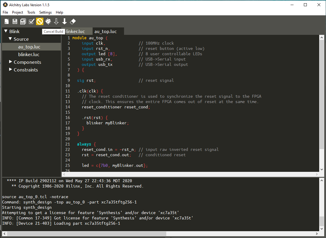
We can now head over to the top level module and instantiate our new module. Note that I’m using an Au, but the module would look the same for the Cu except the name would be cu_top instead of au_top.
module au_top (
    input clk,              // 100MHz clock
    input rst_n,            // reset button (active low)
    output led [8],         // 8 user controllable LEDs
    input usb_rx,           // USB->Serial input
    output usb_tx           // USB->Serial output
  ) {

  sig rst;                  // reset signal

  .clk(clk) {
    // The reset conditioner is used to synchronize the reset signal to the FPGA
    // clock. This ensures the entire FPGA comes out of reset at the same time.
    reset_conditioner reset_cond;

    .rst(rst) {
      blinker myBlinker;
    }
  }

  always {
    reset_cond.in = ~rst_n; // input raw inverted reset signal
    rst = reset_cond.out;   // conditioned reset

    led = c{7b0, myBlinker.out};

    usb_tx = usb_rx;        // echo the serial data
  }
}
Here I added a connection block for the reset signal and created an instance of the blinker module named myBlinker.
Then, in the always block, I connected it to the led output using the concatenation syntax.
The elements inside c{...} get glued together to form a single array. So in our case, we are concatenating seven 0s with the bit from myBlinker.out. This will turn off the 7 most-significant LEDs and connect our blinker signal to the first LED.
You can now build the project by clicking on the hammer icon and then load it onto your board by pressing the solid down arrow icon.
The top LED should now be blinking slightly slower than once a second.
Module Improvements
We can improve our blinker module quite a bit to make it more useful.
First, the LED blinks with a bit of an awkward timing. We can make this exactly a second by counting to 50,000,000 and toggling the LED then.
To do this we need another DFF to store the state of the LED.
  .clk(clk) {
    .rst(rst) {
      dff ctr[28];
      dff led;
    }
  }
In the always block, we can now check to see if ctr.q is 49,999,999 (since 0 to 49,999,999 is 50,000,000 increments) and if it is we can reset it to 0 and toggle the LED.
  always {
    ctr.d = ctr.q + 1;
    if (ctr.q == 49999999) {
      ctr.d = 0;
      led.d = ~led.q;
    }

    out = led.q;
  }
Here I used the bit-wise inversion operator, ~. This inverts every bit of a signal. Since led.q is only one bit wide, it simply flips that bit.
If you remember from before, I said a signal needs to be assigned a value in all circumstances with the exception of DFFs. Since DFFs can actually save their value, if you don’t assign the d input during a clock cycle, the value of the DFF won’t change.
Our module now only stores the values of 0-49,999,999 in ctr but it is still a 28 bit array. This is wasteful as you only need 26 bits to store our values. We could simply change the array size to 26, but if we want to change the max value we would have to recompute this value each time.
Instead, we can use Lucid functions to calculate this for us. We can use $clog2(50000000) which will computer the ceiling log base 2 of the given value. This equates to “how many bits do I need to store this many combinations.” In our case, it’ll evaluate to 26.
dff ctr[$clog2(50000000)];
Speaking of changing the maximum value, we can edit our module to accept this as a parameter so it can be specified when the module is instantiated.
We can do this by adding a parameter list to our module. This comes before the port list.
module blinker #(
    MAX_VALUE = 50000000 : MAX_VALUE > 0
  )(
    input clk,  // clock
    input rst,  // reset
    output out
  ) {
The port list is specified using the #(param, param, param) syntax. Each parameter can be as simple as just a name (in all capitals), or as complex as our example.
In our example, we set a default value of 50,000,000. Default values are typically a good idea unless you want to force a value to be specified at instantiation.
After the default assignment, you can specify a condition the parameter must meet. This condition can (and should) use the parameter itself as well as any parameters declared before it. This condition must evaluate to “true.” If it doesn’t, there will be an error reported when it is instantiated. This allows you to write your module with some assumptions about the parameter value and know that they will be obeyed.
We can then replace the occurrences of 50,000,000 in our module with MAX_VALUE.
module blinker #(
    MAX_VALUE = 50000000 : MAX_VALUE > 0
  )(
    input clk,  // clock
    input rst,  // reset
    output out
  ) {

  .clk(clk) {
    .rst(rst) {
      dff ctr[$clog2(MAX_VALUE)];
      dff led;
    }
  }

  always {
    ctr.d = ctr.q + 1;
    if (ctr.q == MAX_VALUE-1) {
      ctr.d = 0;
      led.d = ~led.q;
    }

    out = led.q;
  }
}
If you build and load the project now, the LED should blink at a rate of once per second.
However, if you go back to the top-level module, you can change the instantiation to look like this.
blinker myBlinker(#MAX_VALUE(25000000));
Now if you build and load the project, the LED will blink twice per second.