Pro Micro RP2040 Hookup Guide
 bboyho
Examples (MicroPython)
The Raspberry Pi foundation has provided the necessary tools, documentation, and examples to get started with the RP2040. If you haven't already, check out the documentation on the Pico. We'll use this as a reference when using the chip on other development boards to fit your needs in this tutorial.
We'll be using the MicroPython examples from this repo using Thonny IDE.
Installing MicroPython on the RP2040
To install MicroPython on the RP2040, users can download the firmware for Raspberry Pi Pico. Head over to the Raspberry Pi Foundation's RP2040 documentation. Click on the tab for the "MicroPython", scroll down to the Drag-and-Drop MicroPython section, and click the download link for the Raspberry Pi Pico.
Note: Since this tutorial was written, MicroPython has built and released new firmware specifically for the RP2040 Pro Micro. The *.uf2 firmware file can be download from the MicroPython website, by clicking the button below:
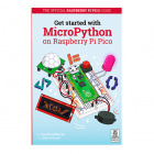
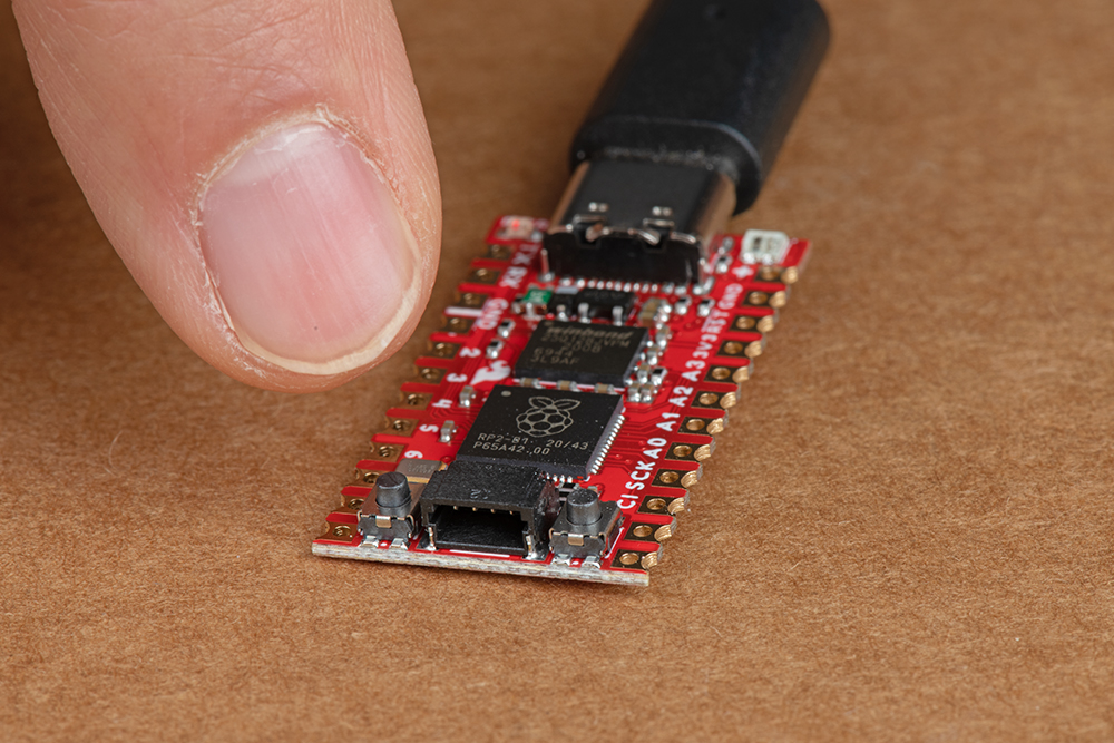
Press and hold the boot button down with one hand.
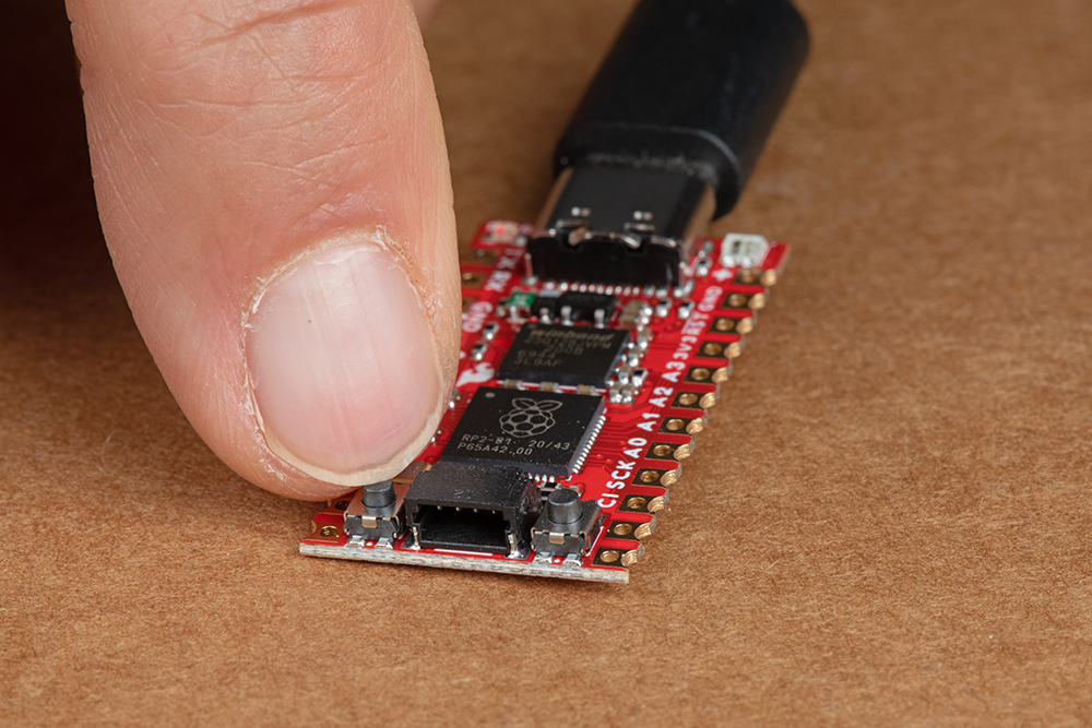
Press the reset button momentarily.
 |
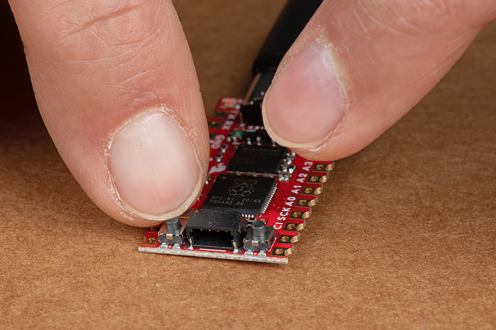 |
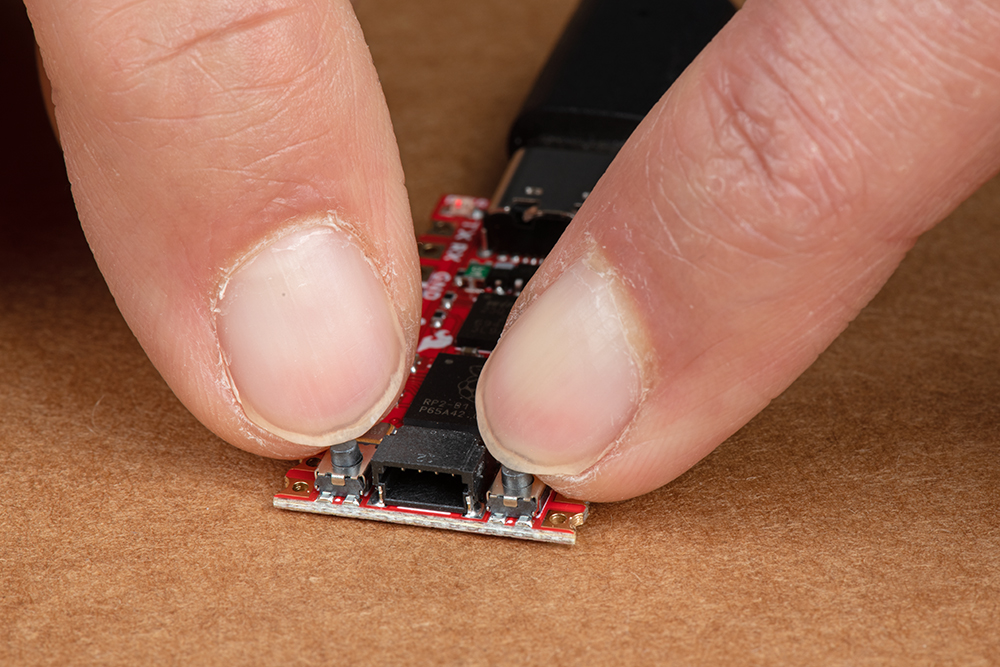
Release the boot button. The board should appear as a removable drive called RPI-RP2.
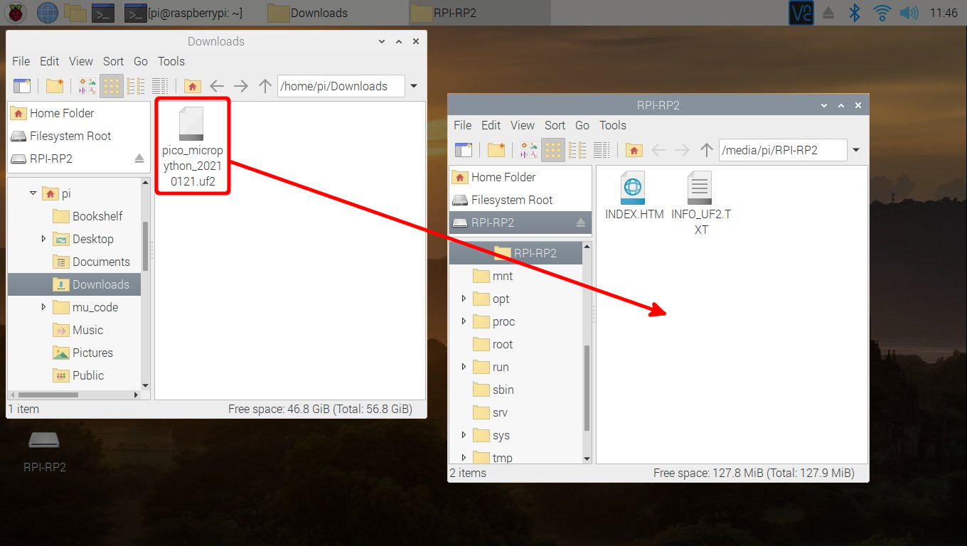
Draw and drop the UF2 file into the "removable drive". The board will automatically reboot. Below is an image highlighting the UF2 file being moved to a the removeable drive on a Raspberry Pi.
Configuring Thonny IDE
&& combines the two commands into a single line and the -y answers "yes" to any prompts. sudo apt update && sudo apt full-upgrade -y
thonny -v
INFO thonny:Thonny version: 3.3.3
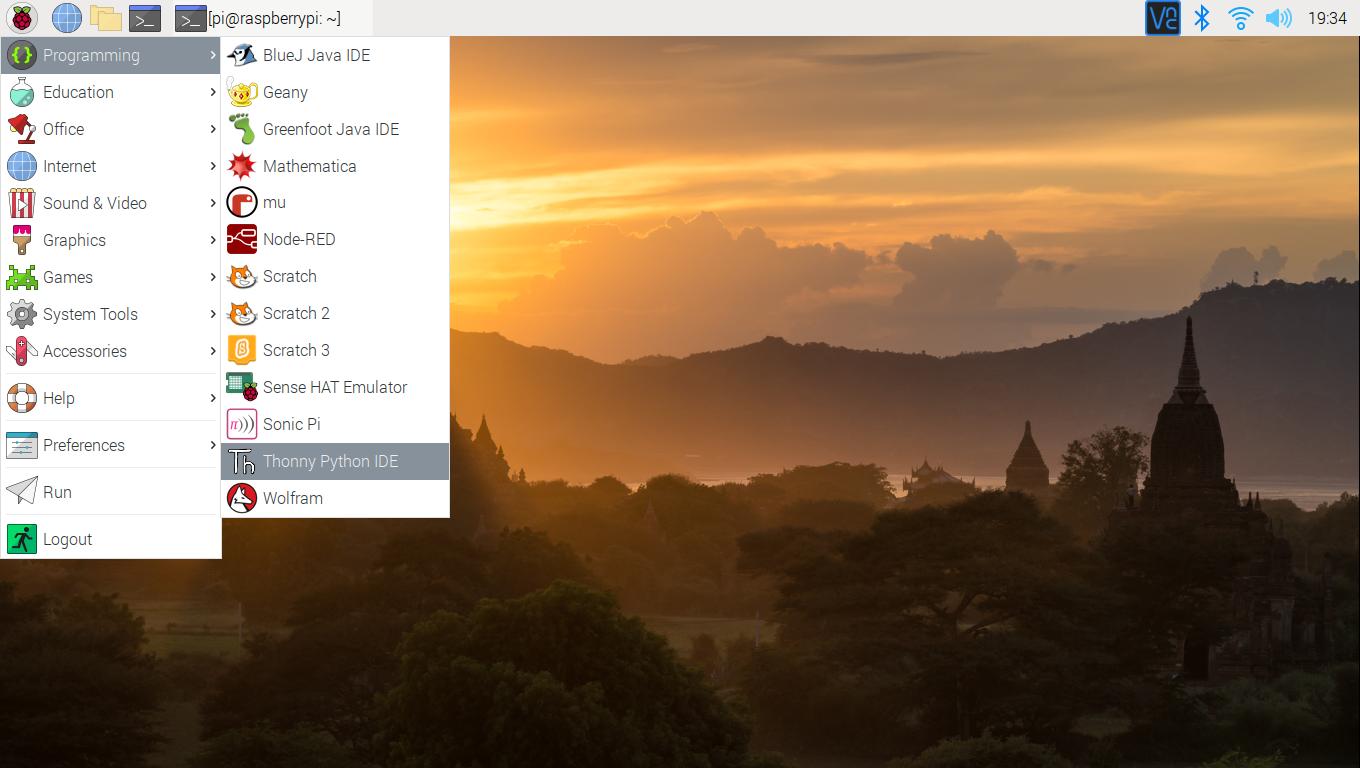
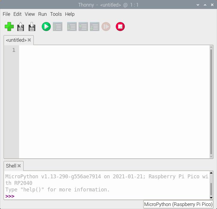
Open Thonny up from the start menu: Raspberry Pi Start Menu > Programming > Thonny Python IDE
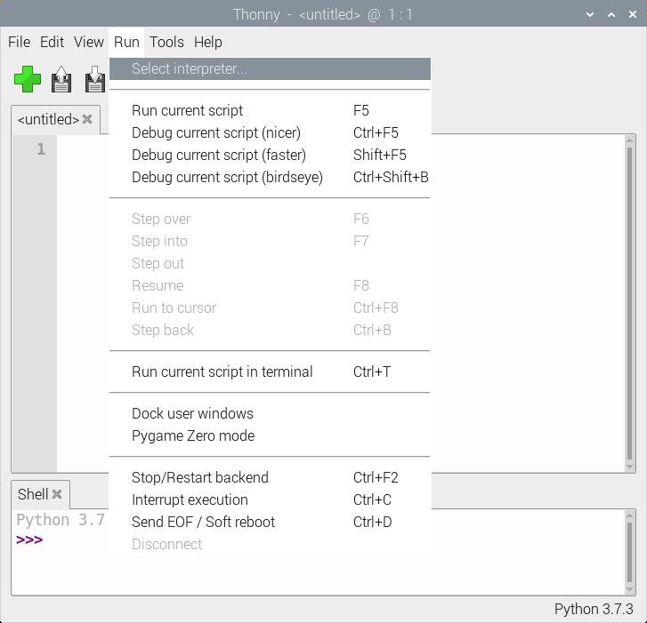
Set Thonny's interpreter for the RP2040. The "Raspberry Pi Pico" will work for the RP2040. Head to the menu and select: Run > Select Interpreter....
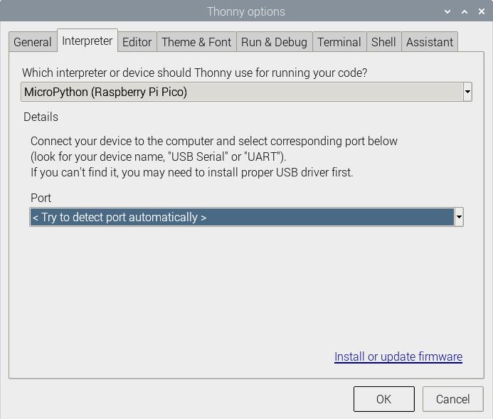
This will open a new window for the Thonny options. In the Interpreter tab, select MicroPython (Raspberry Pi Pico) as the interpreter.
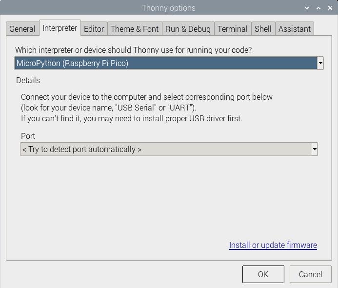
In the same window, make sure to select the option to have Thonny automatically detect the COM port for the board: Port > < Try to detect port automatically >
tty(AMA0 (/dev/ttyAMA0).
Hello World!
To check if this is working open the Thonny IDE, type the following into the editor. Feel free to adjust the message to whatever you prefer.
language:python
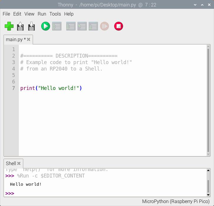
print("Hello world!")
Hit the "Run current script" button. In the Shell, you will see the following output. Sweet!
language:bash
>>> %Run -c %EDITOR_CONTENT
Hello world!
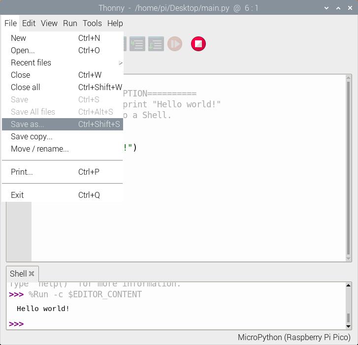
When a window pops up, select Raspberry Pi Pico.
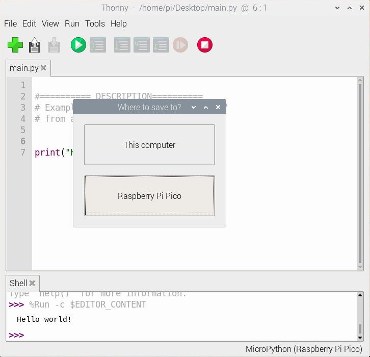
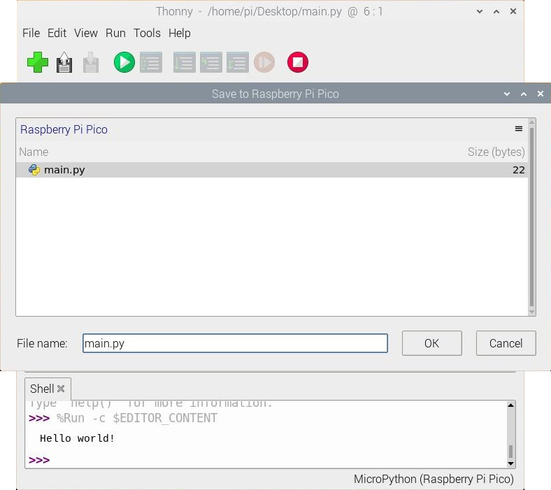
Then save the file as main.py
Just make sure to save any code that was edited on your computer (e.g. Save as... > This computer) before closing Thonny.

Blink
If you have the MicroPython examples saved, head to the following folder in your downloads .../pico-micropython-examples/blink/blink.py . Your code should look like the following. Of course, you can also copy and paste the code provided after the next paragraph as well.
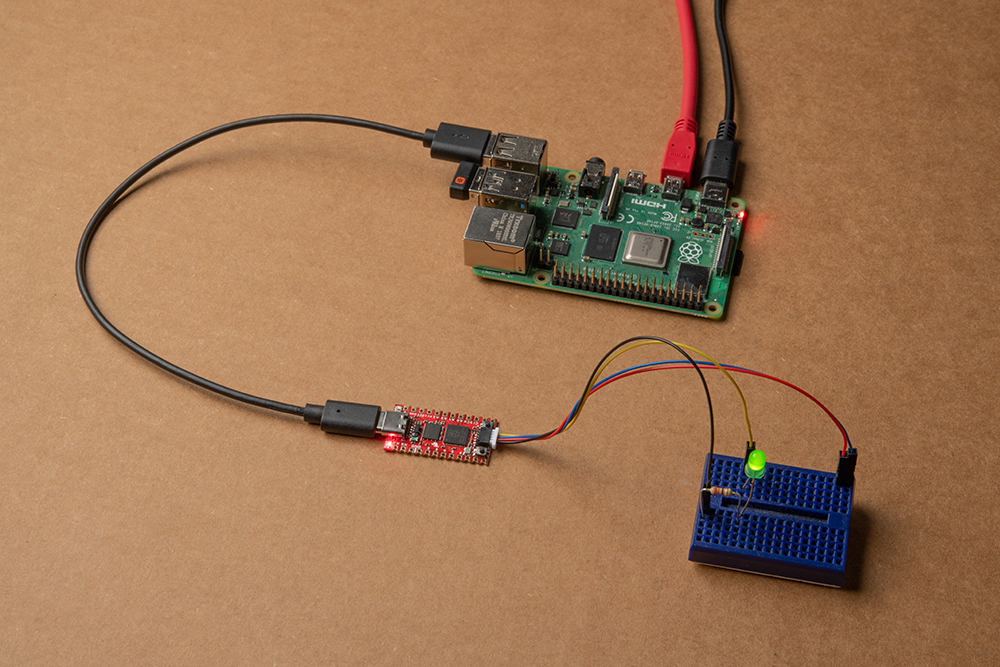
Once you open it in Thonny, adjust the pin number to the GPIO that the LED is connected to. Since we are using the example that was written specifically for the Pico as opposed to the Pro Micro RP2040, we'll need to adjust the pin. In this case, we'll use the RP2040's GPIO17 that is connected to the Qwiic connector so that we do not have to solder pins to the board. This is assuming that we are connecting a current limiting resistor and an LED between the GPIO17 and GND.
language:python
# ========== DESCRIPTION==========
# The following code was originally written by
# the Raspberry Pi Foundation. You can find this
# example on GitHub.
#
#     https://github.com/raspberrypi/pico-micropython-examples/blob/master/blink/blink.py
#
# Note that the GPIO for the LED was adjusted
# for the Pro Micro RP2040. Make sure to use
# a current limiting resistor with the LED.

from machine import Pin, Timer

led = Pin(17, Pin.OUT)
tim = Timer()
def tick(timer):
    global led
    led.toggle()

tim.init(freq=2.5, mode=Timer.PERIODIC, callback=tick)
Hit the "Run current script" button. Once the code runs, you will see the LED blink. If you want the board to run blink every time the board is powered up, just follow the note provided at the end the previous example.
WS2812
If you have the MicroPython examples saved, head to the following folder in your downloads .../pico-micropython-examples/pio/neopixel_ring/neopixel_ring.py . Your code should look like the following. Of course, you can also copy and paste the code provided after the next paragraph as well.
Once you open it in Thonny, adjust the pin number to the GPIO that the LED is connected to for PIN_NUM. Since we are using the example that was written specifically for the Pico as opposed to the Pro Micro 2040, we'll need to adjust the pin. In this case, we'll use the RP2040's GPIO25 that is connected to the WS2812. We will also adjust the NUM_LEDs to 1.
language:python
# ========== DESCRIPTION==========
# Example using PIO to drive a set of WS2812 LEDs.
#
# The following code was originally written by
# the Raspberry Pi Foundation. You can find this
# example on GitHub.
#
#    https://github.com/raspberrypi/pico-micropython-examples/blob/master/pio/neopixel_ring/neopixel_ring.py
#
# Note that the 'NUM_LEDs' was adjusted to 1. Also
# the GPIO for the addressable WS2812 RGB LED called
# `PIN_NUM` was adjusted for the Pro Micro RP2040.

import array, time
from machine import Pin
import rp2

# Configure the number of WS2812 LEDs.
NUM_LEDS = 1
PIN_NUM = 25
brightness = 0.2

@rp2.asm_pio(sideset_init=rp2.PIO.OUT_LOW, out_shiftdir=rp2.PIO.SHIFT_LEFT, autopull=True, pull_thresh=24)
def ws2812():
    T1 = 2
    T2 = 5
    T3 = 3
    wrap_target()
    label("bitloop")
    out(x, 1)               .side(0)    [T3 - 1]
    jmp(not_x, "do_zero")   .side(1)    [T1 - 1]
    jmp("bitloop")          .side(1)    [T2 - 1]
    label("do_zero")
    nop()                   .side(0)    [T2 - 1]
    wrap()


# Create the StateMachine with the ws2812 program, outputting on pin
sm = rp2.StateMachine(0, ws2812, freq=8_000_000, sideset_base=Pin(PIN_NUM))

# Start the StateMachine, it will wait for data on its FIFO.
sm.active(1)

# Display a pattern on the LEDs via an array of LED RGB values.
ar = array.array("I", [0 for _ in range(NUM_LEDS)])

##########################################################################
def pixels_show():
    dimmer_ar = array.array("I", [0 for _ in range(NUM_LEDS)])
    for i,c in enumerate(ar):
        r = int(((c >> 8) & 0xFF) * brightness)
        g = int(((c >> 16) & 0xFF) * brightness)
        b = int((c & 0xFF) * brightness)
        dimmer_ar[i] = (g<<16) + (r<<8) + b
    sm.put(dimmer_ar, 8)
    time.sleep_ms(10)

def pixels_set(i, color):
    ar[i] = (color[1]<<16) + (color[0]<<8) + color[2]

def pixels_fill(color):
    for i in range(len(ar)):
        pixels_set(i, color)

def color_chase(color, wait):
    for i in range(NUM_LEDS):
        pixels_set(i, color)
        time.sleep(wait)
        pixels_show()
    time.sleep(0.2)

def wheel(pos):
    # Input a value 0 to 255 to get a color value.
    # The colours are a transition r - g - b - back to r.
    if pos < 0 or pos > 255:
        return (0, 0, 0)
    if pos < 85:
        return (255 - pos * 3, pos * 3, 0)
    if pos < 170:
        pos -= 85
        return (0, 255 - pos * 3, pos * 3)
    pos -= 170
    return (pos * 3, 0, 255 - pos * 3)


def rainbow_cycle(wait):
    for j in range(255):
        for i in range(NUM_LEDS):
            rc_index = (i * 256 // NUM_LEDS) + j
            pixels_set(i, wheel(rc_index & 255))
        pixels_show()
        time.sleep(wait)

BLACK = (0, 0, 0)
RED = (255, 0, 0)
YELLOW = (255, 150, 0)
GREEN = (0, 255, 0)
CYAN = (0, 255, 255)
BLUE = (0, 0, 255)
PURPLE = (180, 0, 255)
WHITE = (255, 255, 255)
COLORS = (BLACK, RED, YELLOW, GREEN, CYAN, BLUE, PURPLE, WHITE)

print("fills")
for color in COLORS:
    pixels_fill(color)
    pixels_show()
    time.sleep(0.2)

print("chases")
for color in COLORS:
    color_chase(color, 0.01)

while True:
    print("rainbow")
    rainbow_cycle(0)
Hit the "Run current script" button. Once the code runs, it will display each color at "0.2" brightness. The LED will then animate. Since there is only one LED attached, it will look like it will be blinking through the colors. Once the board jumps into the while loop, the LED will begin cycling between colors smoothly. Remember, you can have the board run the example every time the board is powered up by following the note provided in an earlier example.
If you are looking to simplify the code, you can also use the library written for the WS2812. This saves some of the functions in a separate file. Just make sure to adjust the GPIO to connect to the WS2812(s) and the number of LEDs.