PicoBuck Hookup Guide v12
 SFUptownMaker
 PicoBuck Overview
Since the PicoBuck is a constant current driver, the current drawn from the supply will drop as supply voltage rises. At 12V, the PicoBuck drives the three LEDs on our Luxeon Rebel Triple Play board at 350mA per LED while drawing less than 350mA total from the power supply. You can also use the board to drive any high power LED like the ones listed below. The PicoBuck is perfect for using with the triple output high power RGB LED or driving a few high power LEDs in series.
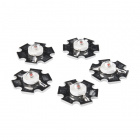
LED - 3W Aluminum PCB (5 Pack, Red)
COM-13106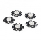
LED - 3W Aluminum PCB (5 Pack, Blue)
COM-13107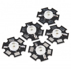
LED - 3W Aluminum PCB (5 Pack, Green)
COM-13185Control Pins
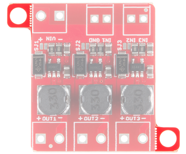
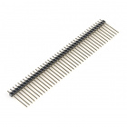
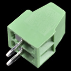
Three signal inputs are provided for dimming control. You can use the PWM signal from an Arduino or your favorite microcontroller to dim each channel individually, or you can tie them all to the same PWM for simultaneous dimming. A separate ground pin (labeled GND) is provided to reference against the controlling module for accuracy. The pin spacing for the two pairs of pins is 0.1", but the two pairs are slightly 0.2" apart, to allow for a 2.54mm pitch screw terminal pair to be used, or for a five-position standard 0.1" header with the middle pin removed.

Dimming can be done by an analog voltage (20%-100% of max current by varying voltage from 0.0V-2.5V) or by PWM (so long as PWM minimum voltage is less than 0.4V and maximum voltage is more than 2.4V but not more than 5V) for a full 0-100% range. Avoid analog voltages above 5V, as these may damage the part.
Input Voltage (VIN)
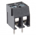
The power supply pads are sized for 3.5mm screw terminals as are the output pads.
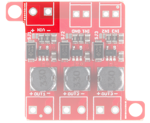
3.5mm screw terminals or hookup wire can be used to connect to the pins depending on your personal preference.


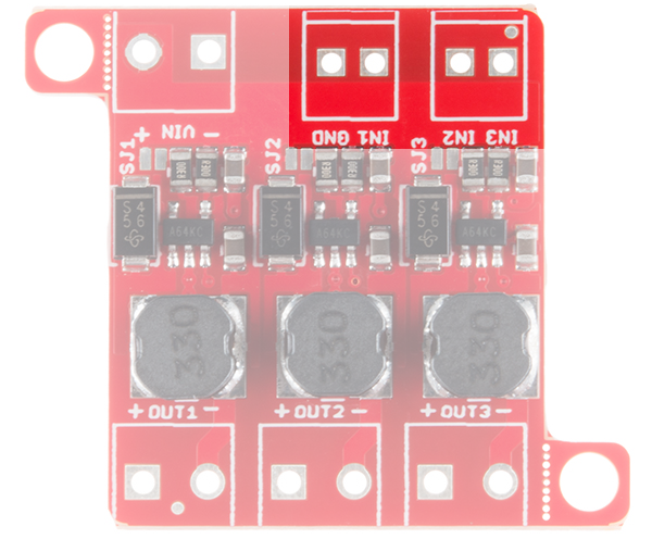
Channel Outputs
The output pads are also sized for 3.5mm screw terminals. Each output is independent from the other two.
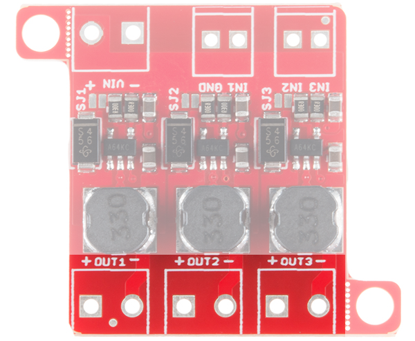
Default Current Output Per Channel
A small jumper is provided for each channel to allow you to increase the drive strength from 330mA to 660mA. More information on this can be found below.
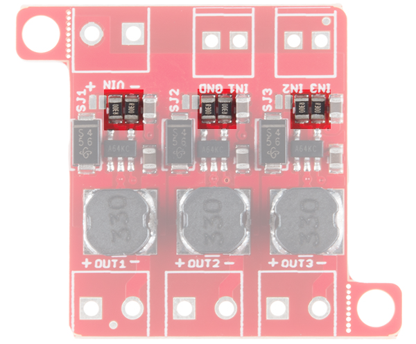
Alternative Current Output
It is possible to increase the maximum current of the PicoBuck board up to 1A per channel; to do so, replace the three current sense resistors with smaller values. To calculate the new value for the resistor, use this formula:
Thus, for a 1A current, you'd want a 0.1Ω resistor. Don't forget to be wary of current ratings. At 1A, the sense resistor will be dissipating 1/10W, so you probably want a resistor of at least 1/8W rating. The package is a standard 0805.
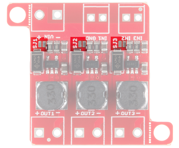
Closing the Current Setting Jumpers
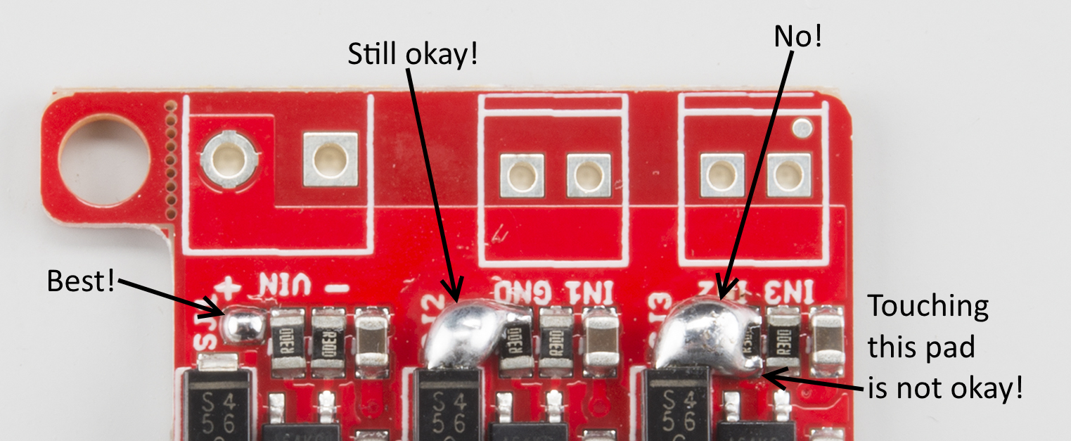
As you can see from the image above, the solder jumper doesn't need to be closed particularly neatly. All of the pads in its vicinity are connected to it anyway, so if you glob a little extra solder on, it's no big deal. Just be careful not to actually short the resistors, as in the rightmost circuit!
Mounting Holes
Two mounting holes for 4-40 or M3 screws are provided on either side of the board. They are perforated so they can be easily snapped off with a pair of pliers, if a smaller footprint is desired.