OpenLog Hookup Guide
Hardware Overview
Power
The OpenLog runs at the following settings:
| VCC Input | 3.3V-12V (Recommended 3.3V-5V) |
|---|---|
| RXI Input | 2.0V-3.8V |
| TXO Output | 3.3V |
| Idle Current Draw | ~2mA-5mA (w/out microSD card), ~5mA-6mA (w/ microSD card) |
| Active Writing Current Draw | ~20-23mA (w/ microSD card) |
The OpenLog's current draw is about 20mA to 23mA when writing to a microSD. Depending on the size of the microSD card and its manufacturer, the active current draw can vary when the OpenLog is writing to the memory card. Increasing the baud rate will also pull more current.
Microcontroller
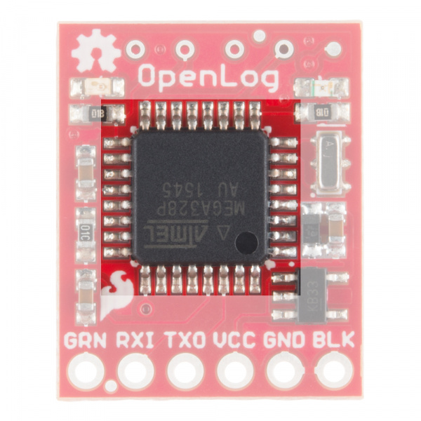
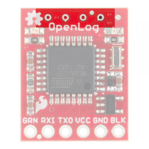
The OpenLog runs off of an onboard ATmega328, running at 16MHz thanks to the onboard crystal. The ATmega328 has the Optiboot bootloader loaded on it, which allows the OpenLog to be compatible with the "Arduino Uno" board setting in the Arduino IDE.
Interface
Serial UART
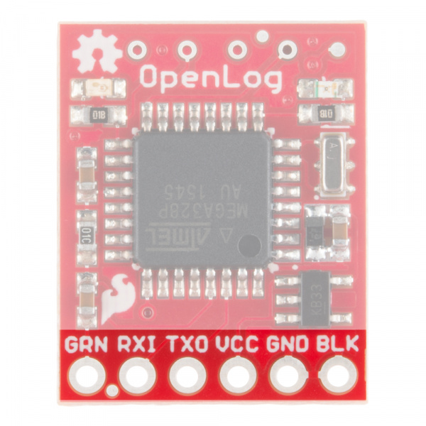
The primary interface with the OpenLog is the FTDI header on the board edge. This header is designed to plug directly into an Arduino Pro or Pro Mini, which allows the microcontroller to send the data over a serial connection to the OpenLog.
SPI
There are also four SPI test points broken out on the opposite end of the board. You can use these to reprogram the bootloader on the ATmega328.
The latest OpenLog (DEV-13712) breaks out these pins on smaller plated through holes. If you need to use an ISP to reprogram or upload a new bootloader to the OpenLog, you can use pogo pins to connect to these test points.
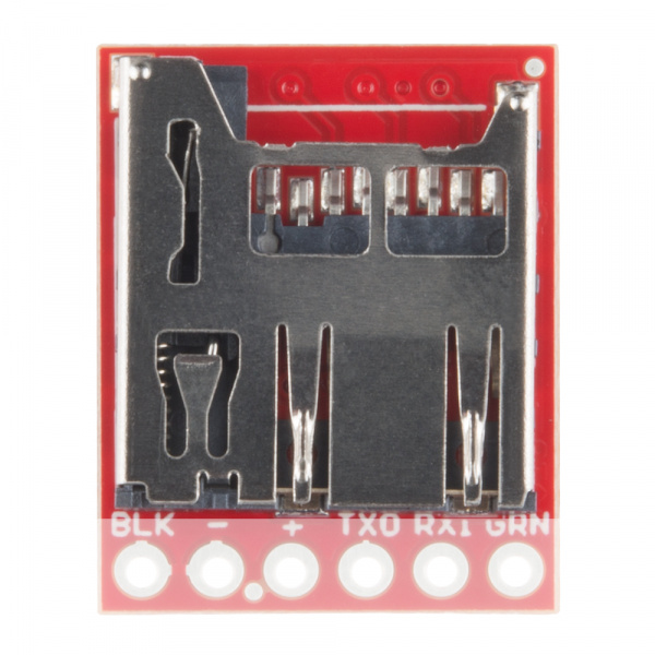
The final interface for communicating with the OpenLog is the microSD card itself. To communicate, the microSD card requires SPI pins. Not only is this where the data is stored by the OpenLog, but you can also update the OpenLog's configuration via the config.txt file on the microSD card.
microSD Card
All data logged by the OpenLog is stored on the microSD card. The OpenLog works with microSD cards that involve the following features:
- 64MB to 32GB
- FAT16 or FAT32
Status LED
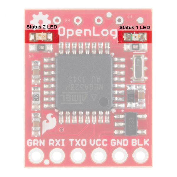
There are two status LEDs on the OpenLog to help you with troubleshooting.
- STAT1 - This blue indicator LED is attached to Arduino D5 (ATmega328 PD5) and toggles on/off when a new character is received. This LED blinks when Serial communication is functioning.
- STAT2 - This green LED is connected to Arduino D13 (SPI Serial Clock Line/ ATmega328 PB5). This LED only blinks when the SPI interface is active. You will see it flash when the OpenLog records 512 bytes to the microSD card.
