MPL3115A2 Pressure Sensor Hookup Guide
Contributors:
 Nate
Nate
Hooking It Up
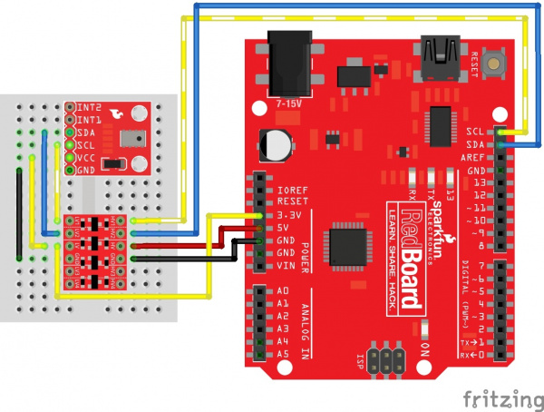
Wiring up the MPL3115A2 pressure sensor is very easy! After soldering the headers of your choice on the board, you'll need to convert the logic between the 5V and the sensor using a logic level converter.
You'll need 5v and 3.3V for VCC, one for GND, and two data lines for I2C communication from your Arduino. You may also use the A4 and A5 pins on older Arduino Boards that do not have SDA and SCL broken out.
Note: This breakout board has built-in 1kΩ pull up resistors for I2C communications. If you're hooking up multiple I2C devices on the same bus, you may need to disable the other resistors on the bus.
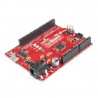
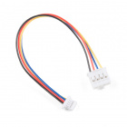
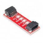
Note: If you have a RedBoard Qwiic, there is an alternative to use the built-in logic level converter using the qwiic adapter and cable or jumpers that can be used to adjust the voltage level to 3.3V.
Hookup Table
With respect to the logic level converter, the pin connections starting from LV1 are listed in the table below.
| MPL3115A2 | Logic Level Converter (Low Side) | Logic Level Converter (High Side) | 5V Arduino w/ Atmega328P |
|---|---|---|---|
| SCL | LV1 | HV1 | SCL (or A5) |
| SDA | LV2 | HV2 | SDA(or A4) |
| VCC | LV | 3.3V | |
| HV | 5V | ||
| GND | GND | GND | GND |
Note: Not all microcontrollers use the same pin for SDA and SCL. If you are using a different architecture that is not the Atmega328P, make sure to edit the code accordingly if you use those pins instead.


