MiniGen Hookup Guide
 SFUptownMaker
Assembly
The MiniGen works as both a normal breakout board and as an add-on to the Arduino Pro Mini boards. Note that the SparkFun Pro Micro, Arduino Nano, and other similar form-factor boards won't work, as they don't have the necessary SPI pins in the same location.
Output connection
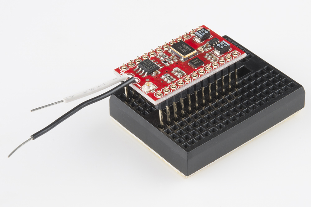
Before you go any further, think about what you're going to do with the output of the MiniGen. Do you want bare wires (as I've done, here) on the output pads? Are you going to use the u.FL connector? .1" header pins? Make that decision now, and put your desired connector on the board.
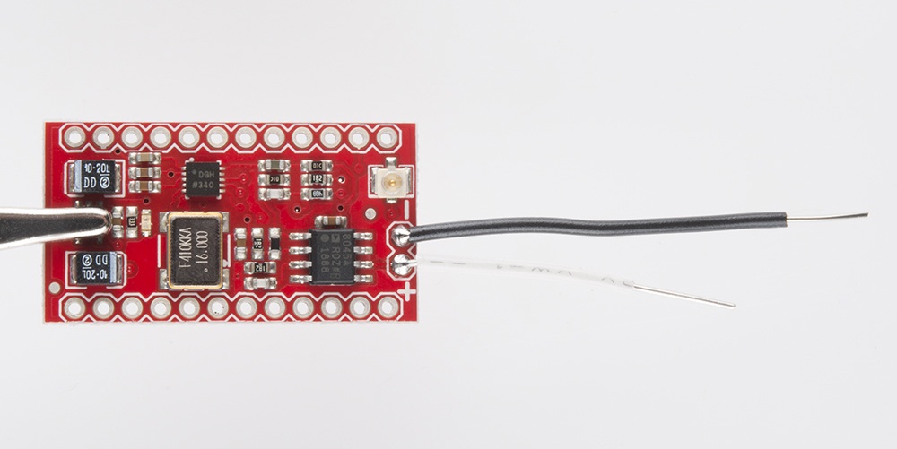
I've elected to put two solid-core wires on this board, so I can plug the ends into a breadboard or clip a scope probe onto them. I left the lengths uneven to avoid having them touch and short.
Adding headers
We'll start by explaining how to put male pin headers on the MiniGen. This will let us plug it into a breadboard easily, or into female headers soldered onto an Arduino Pro Mini (which we'll go over later).
Start by trimming the pin headers to the right length. You'll need 12 pins per side.
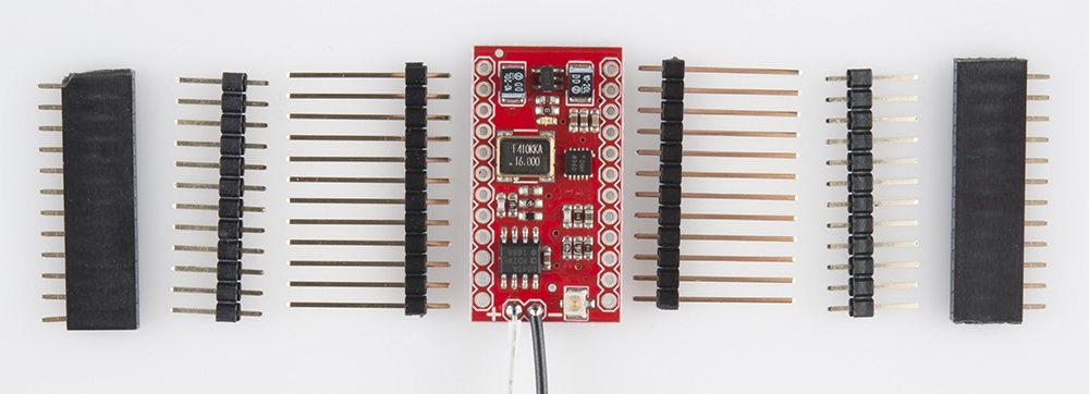
You can, of course, use any style of header you want: on display here are our female headers, our short male headers, and our long male headers. I'll show you some options with each of these.
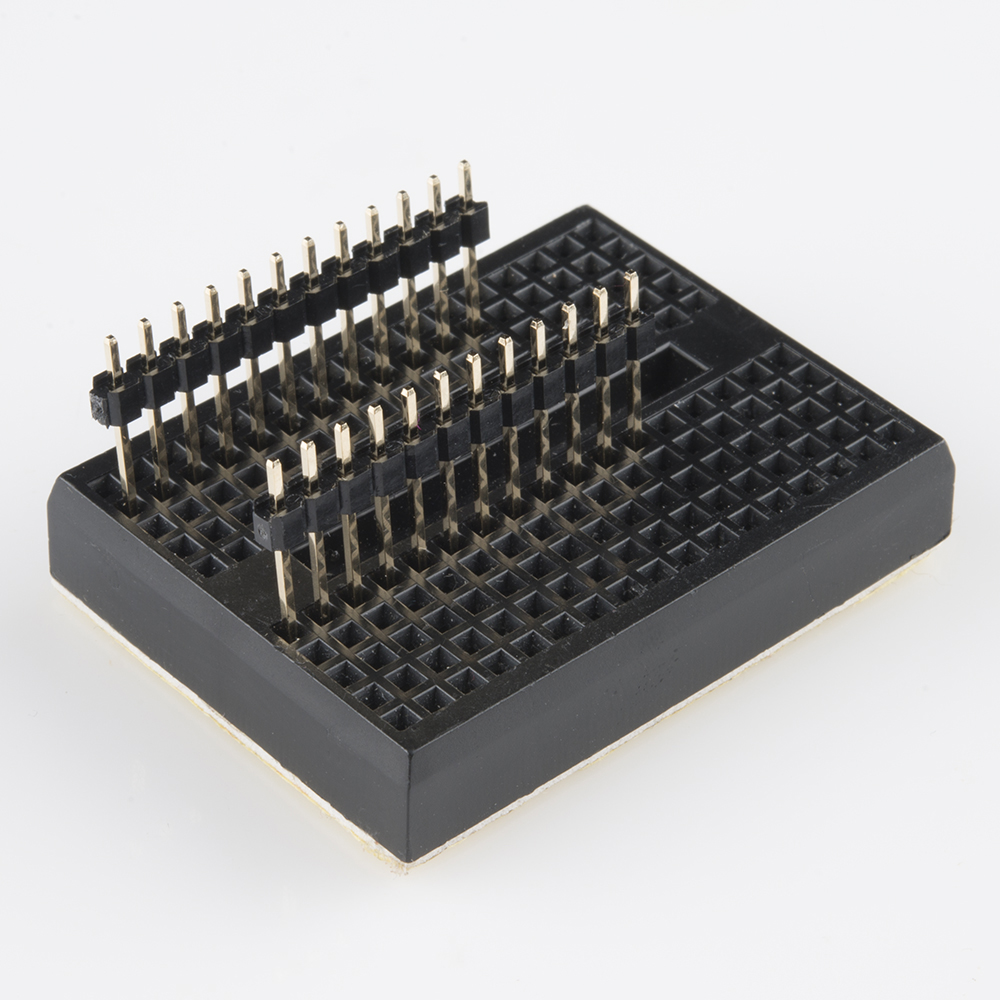
The easiest way to ensure that the pins are nicely perpendicular to your board (and thus, will mate easily with another board or breadboard) is to insert them into a breadboard. The width of the MiniGen is such that one row of pins inserted right next to the center line will place the other row of pins one column off the edge on the other side, as pictured below.
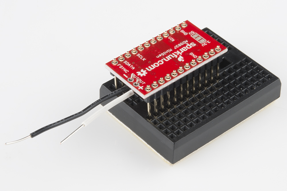
Once the pin headers are in place, you can lower the MiniGen board onto them. The board can be soldered on component side up or component side down; depending on what you plan to do with it, one of those is likely to be better.
If you put the board on the headers component side down, as shown below, you can see the pin labels. That makes this method better for use as a breakout board; however, you'll be unable to put the board on the top side of a Pro Mini. We'll talk about that in a minute.
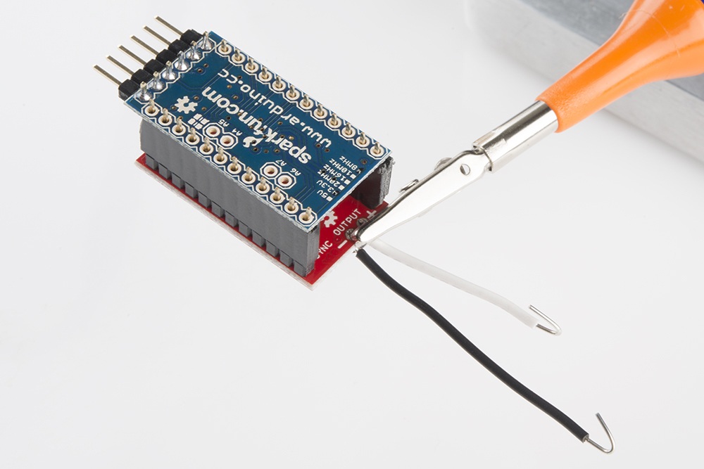
Flipping the board over, component side up, will allow you to mount it on a Pro Mini board that has female headers on its top side. I'll show you both of these cases fully assembled, so you can see the implications of each.
If you plan to put female headers on your Pro Mini, I strongly suggest that you solder down the male headers on the MiniGen, then use those to hold the female headers at an auspicious angle on the Pro Mini. That way, they'll mate smoothly in the future.
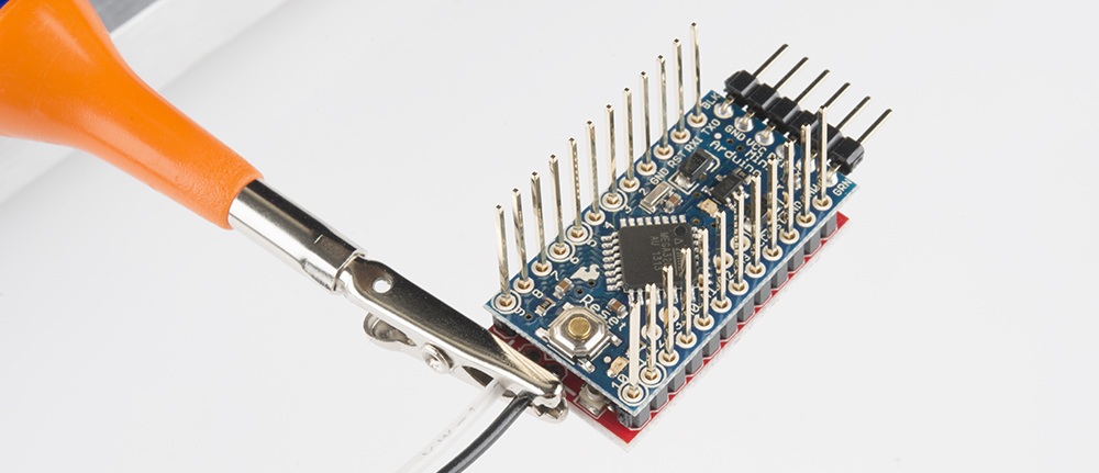
You can see a couple of points: the pin headers on the MiniGen have been soldered in with the long pins on the opposite side from the components, and the receptacles are on the component side of the Pro Mini.
As I mentioned above, if you elected to put your headers in with the components "down", you can't put the MiniGen on top of your Pro Mini. However, if you use our long breakaway male headers, you can put the pins in from the bottom, and they'll protrude on top enough for you to stack another board on top, such as the MiniFet Shield or a Pro Mini Protoshield. This has the disadvantage of covering up the u.FL connector on top of the board, but that may not be a problem for you.
If you use this method, be certain there's a gap between the bottom of the Pro Mini and the components on the top of the MiniGen.