Mini FET Shield Hookup Guide
This Tutorial is Retired!
This tutorial covers concepts or technologies that are no longer current. It's still here for you to read and enjoy, but may not be as useful as our newest tutorials.
 Joel_E_B
Board Overview
There's a lot happening on this tiny board. Let's break down each section and discuss in more detail how to use the Mini FET Shield.
Power
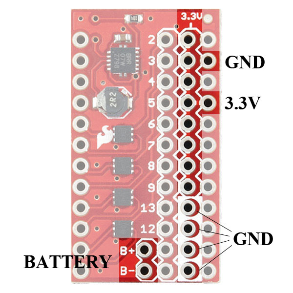
The Mini FET shield was designed with battery power in mind. On the shield, you'll notice the B+ and B-. Here, you can attach any battery between 1.8-5.5V, and the on-board regulator will regulate or boost it to 3.3V accordingly. This allows you to create mobile, battery powered projects that use AA, AAA, 9V, or LiPo batteries. It also provides a constant voltage to your devices, so motors and other peripherals will work at full force, even when the battery is nearing depletion.
The TPS61200 IC handles all the boosting/regulating. Keep in mind this IC is rated to deliver 600mA of output current. However, we've successfully put 2A through it. As always, be cautious about exceeding the maximum ratings for any device.
NOTE: This shield DOES NOT contain a battery charger. If you need to charge your battery, please see our charger offering.
The GND and 3.3V labeled on the right side indicate which pins are used to power the Pro Mini. Alternatively, if you chose to not use battery power for your project, you can power the shield through the Arduino Pro Mini. Note that because of this power scheme, this shield will only work with 3.3V Arduino Pro Mini and NOT the 5V Pro Mini.
Last, there is an 8-pin 3.3V rail (one for each MOSFET) and a 4-pin GND rail (one for the four remaining digital I/Os). These are conveniently placed next to the digital pins to allow buttons, motors, and other parts to be connected easily.
The MOSFETS
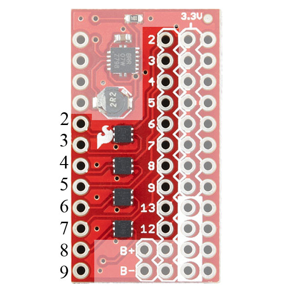
These FDMA1024NZs are the stars of the show. Each of these ICs contain two N-channel MOSFETs, which is a type of transistor, and each is connected to pins 2-9, leaving us with 8 FETs to control. Transistors work just like electronically controlled switches. Thus, in order to turn on each transistor, we must pull the associated pin HIGH. This will allow the current to flow from the 3.3V source through your peripheral, through the transistor, and to ground, thus completing the circuit. This will become clearer as we connect more parts in the next section.
Digital I/O
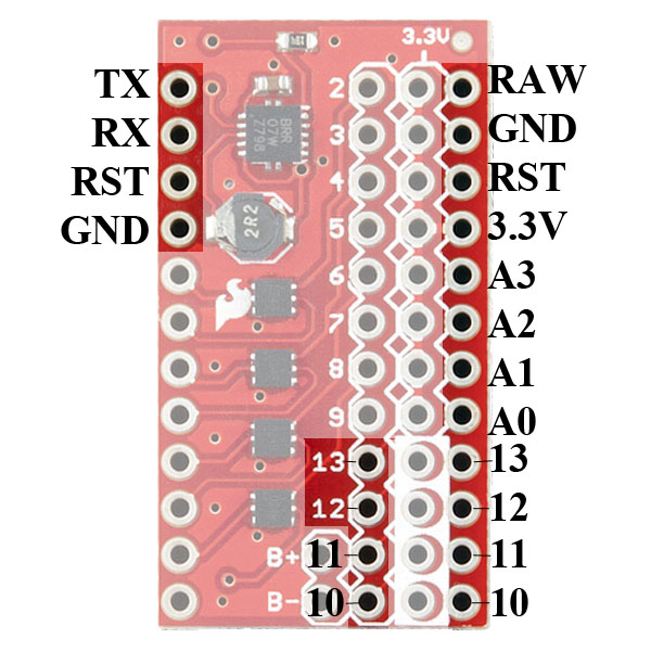
Finally, there are four leftover digital I/Os:** pins 10-13**. These can be used as inputs or outputs and have a GND bus next to them to easily connect buttons and switches. If you do decide to add some inputs to these pins, remember to configure your pins as INPUT_PULLUP to turn on the internal pull-up resistors on the Pro Mini.
The remaining pins are labeled for your convenience. These pins don't play a role in the function of the shield. However, you cam use a variety of headers, such as these stackable headers, to break out these pins, if you need. You can also solder wire directly to these pins.