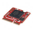
The MicroMod Alorium Sno M2 Processor Board features the Snō System on Module (SoM) from Alorium Technology adapted to the MicroMod M.2 processor form factor. Snō's FPGA provides a reconfigurable hardware platform that hosts an 8-bit AVR instruction set, compatible with the ATmega328, making Snō fully compatible with the Arduino IDE. Snō SoM has a compact footprint, making it ideal for space-constrained applications and an obvious addition to our MicroMod form factor for prototyping.
Alorium Technology provides a library of custom logic called Xcelerator Blocks (XBs) through the Arduino IDE that accelerate specific functionality that is slow, problematic, or even impossible for an 8-bit microcontroller. This library includes XBs such as Servo Control, Quadrature, Floating Point Math, NeoPixel, and Enhanced Analog-to-Digital Converter. Alorium also notes a XB roadmap where future XBs will be implemented based on feedback from early adopters and new potential customers.
To follow along with this tutorial, you will need the following materials. You may not need everything though depending on what you have. Add it to your cart, read through the guide, and adjust the cart as necessary.
If you aren't familiar with the MicroMod ecosystem, we recommend reading here for an overview. We recommend reading here for an overview if you decide to take advantage of the Qwiic connector.
 |
|
| MicroMod Ecosystem | Qwiic Connect System |
If you aren’t familiar with the following concepts, we also recommend checking out these tutorials before continuing.
All of our MicroMod Processor Boards come equipped with the M.2 MicroMod Connector, which leverages the M.2 standard and specification to allow you to install your MicroMod Processor Board on your choice of carrier board. Most of the pins use a common pinout to ensure cross platform compatibility.
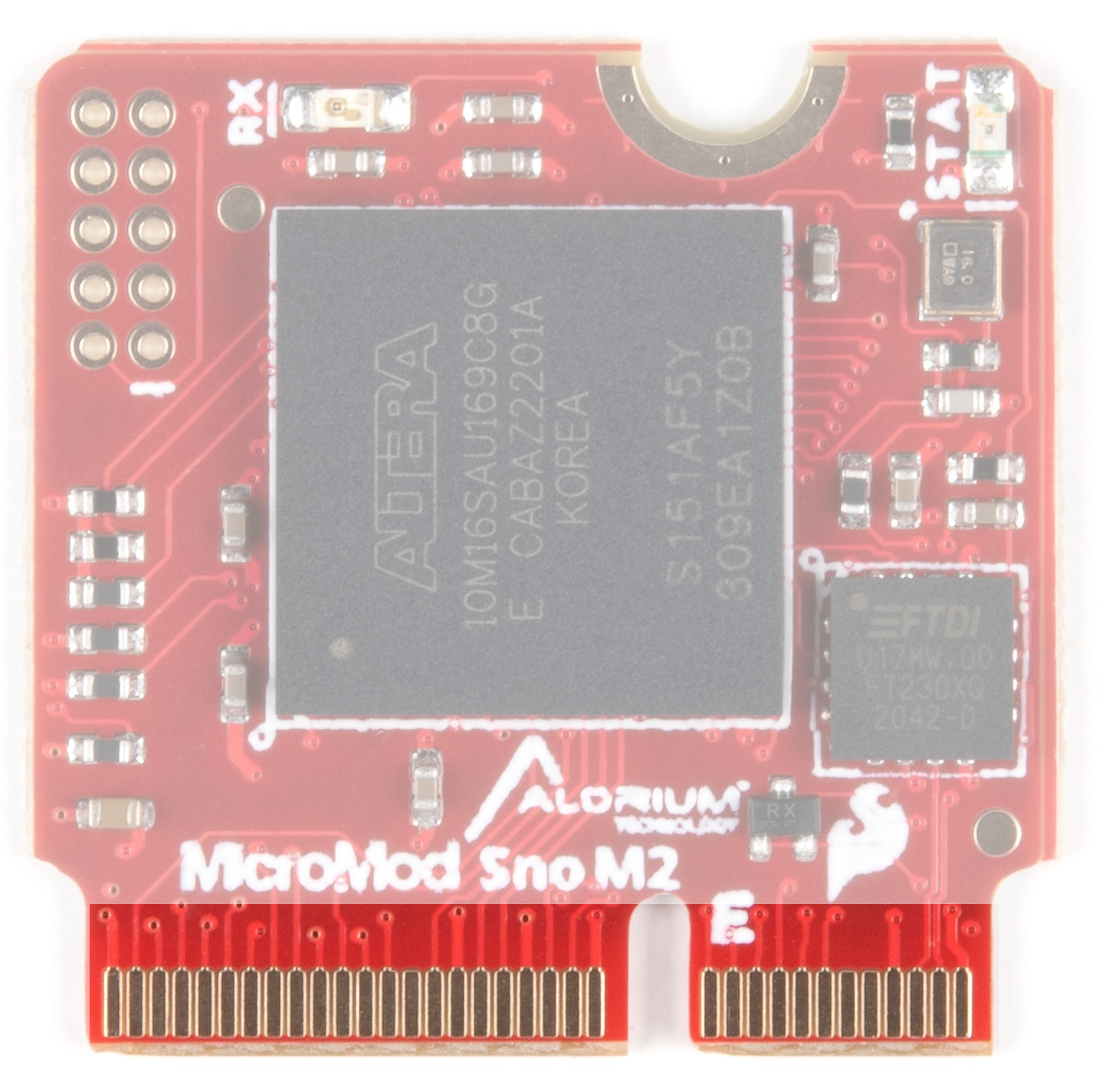
The Alorium Technology Sno FPGA provides a reconfigurable hardware platform that hosts an ATmega328 instruction set compatible microcontroller. The FPGA also provides the ability to implement custom logic that accelerates specific functionality that is slow, problematic or even impossible for an 8-bit microcontroller.

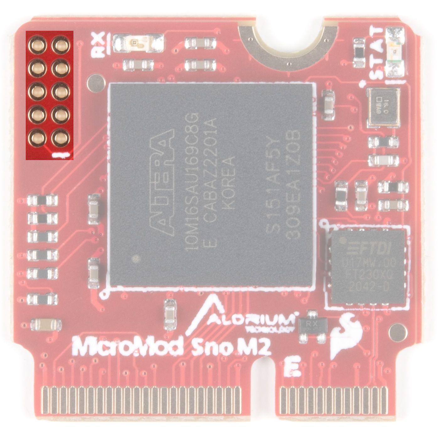
The JTAG interface on Sno M2 is primarily used during manufacturing to load the production FPGA image. For advanced users, JTAG can be used for creating bare-metal FPGA designs and directly flashing a new image to the FPGA.
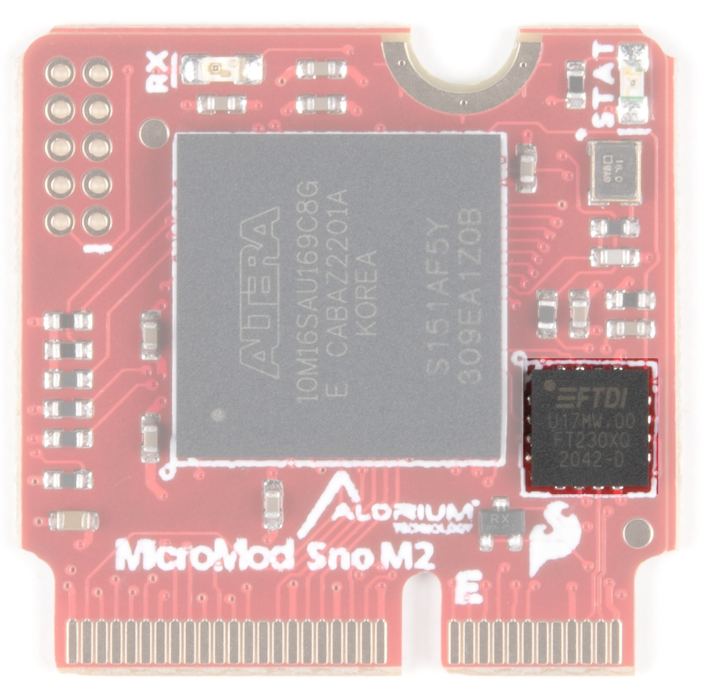
The FTDI facilitates USB communication - drivers for the FTDI chip may need to be installed. Please see the How to Install FTDI drivers tutorial if you need help installing these drivers.
There are two LEDs on the Sno Processor Board. An RX LED and a STAT LED.
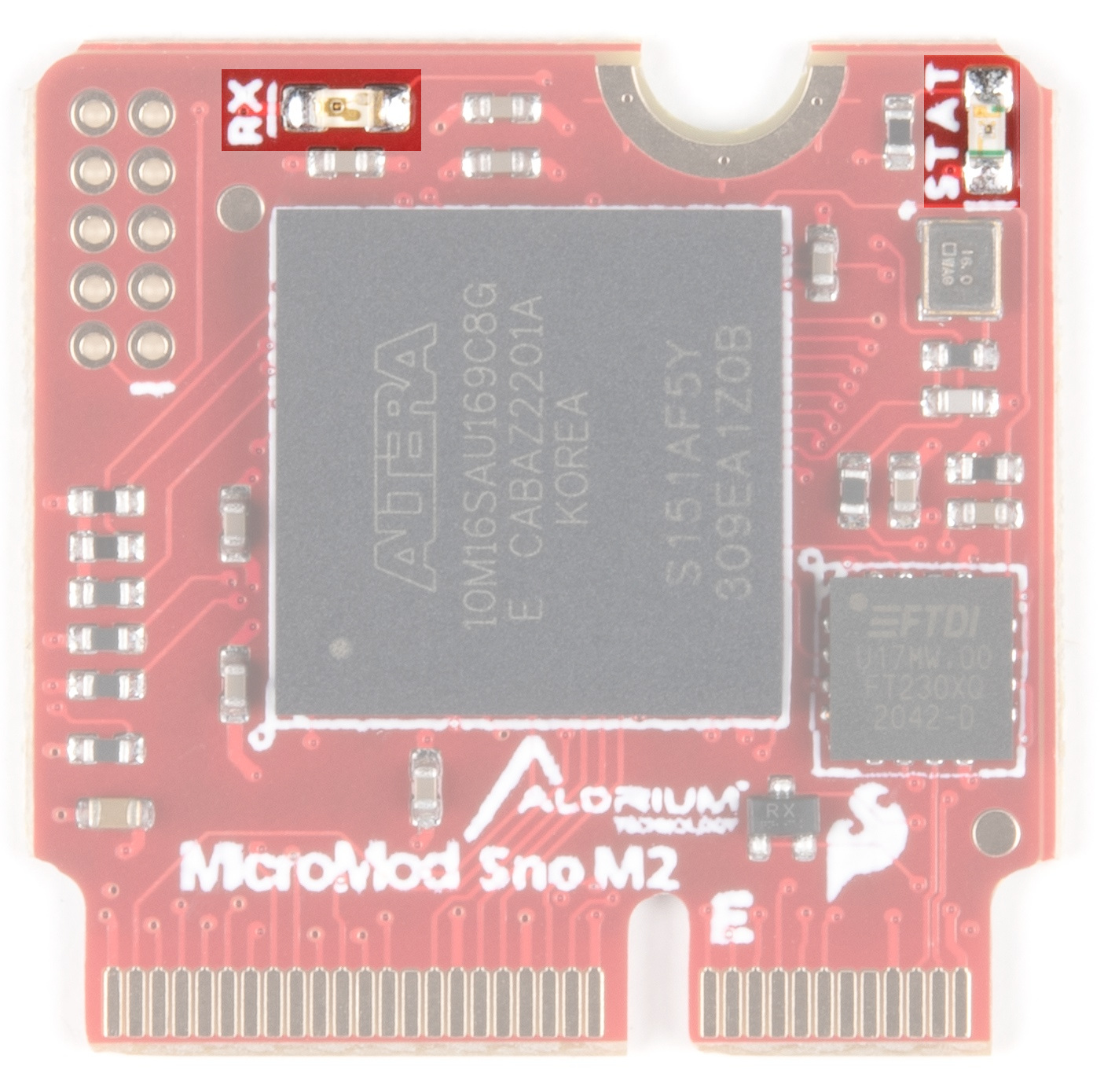
RX LED - The RX LED indicates activity on the USB serial port.
STAT LED - A STAT LED is added to the top side of the board. This is useful debugging or as a status indicator.
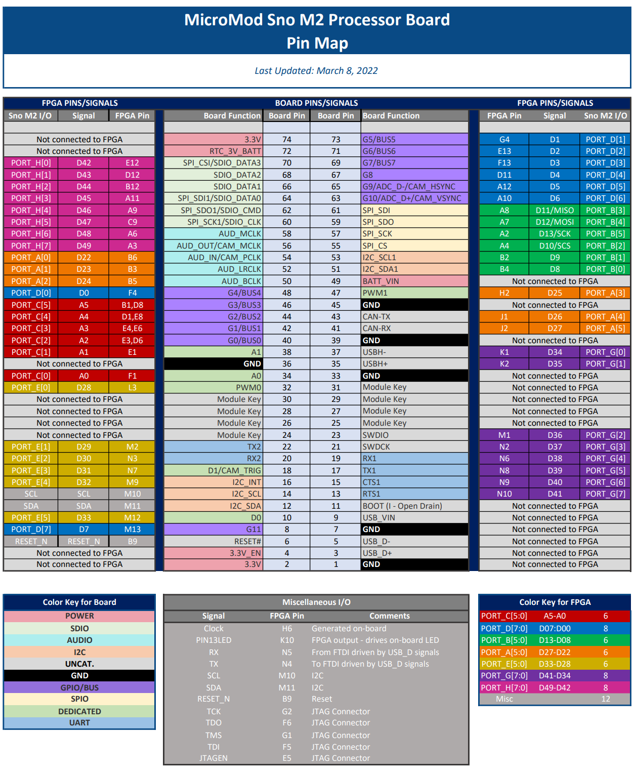
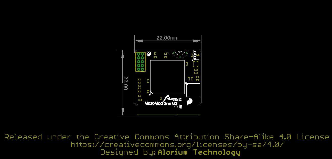
The complete pin map is shown here or you can refer to the schematic. You can also download the PDF version of the pin map here.
The board takes advantage of the standard MicroMod form factor.
If you have not already, make sure to check out the Getting Started with MicroMod: Hardware Hookup for information on inserting your Processor Board into your Carrier Board.
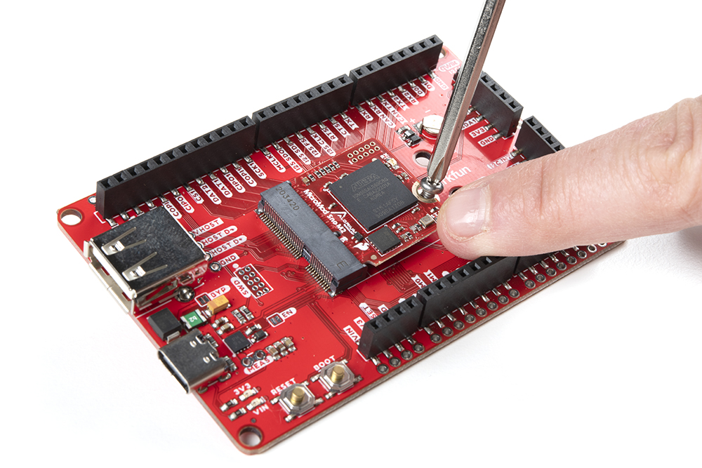
After inserting the MicroMod Alorium Sno M2 processor board into a carrier board, your setup may look like the following.
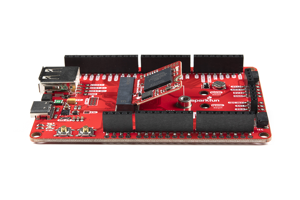
Go ahead and secure the Processor Board by gently pressing it down and tightening the screw (not too much though).
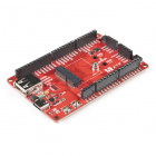
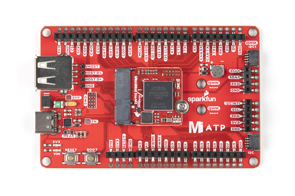
For simplicity, we'll be using the MicroMod ATP Carrier Board to program the board. At a minimum, your setup should look like the image below with the MicroMod Alorium Sno M2 Processor Board.
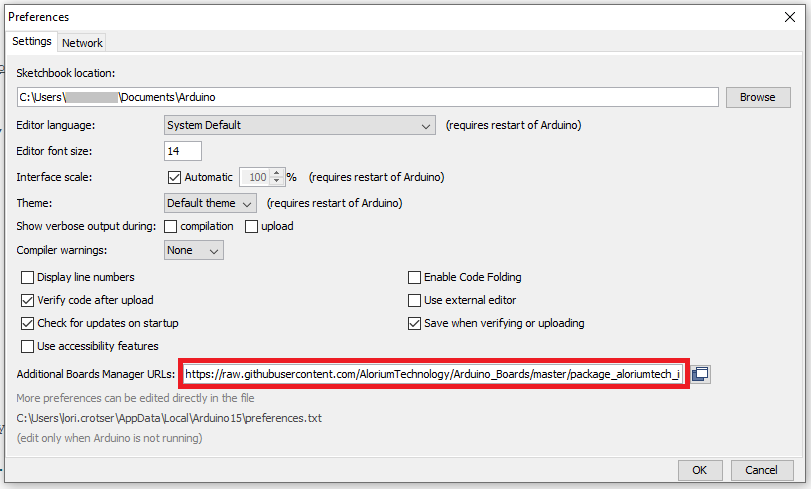
In your Arduino IDE menu bar, go to File > Preferences and locate the ‘Additional Boards Manager URLs’ input field. Paste the following URL into the “Additional Boards Manager URLs” input field:
language:json
https://raw.githubusercontent.com/AloriumTechnology/Arduino_Boards/master/package_aloriumtech_index.json
It should look something like the following:
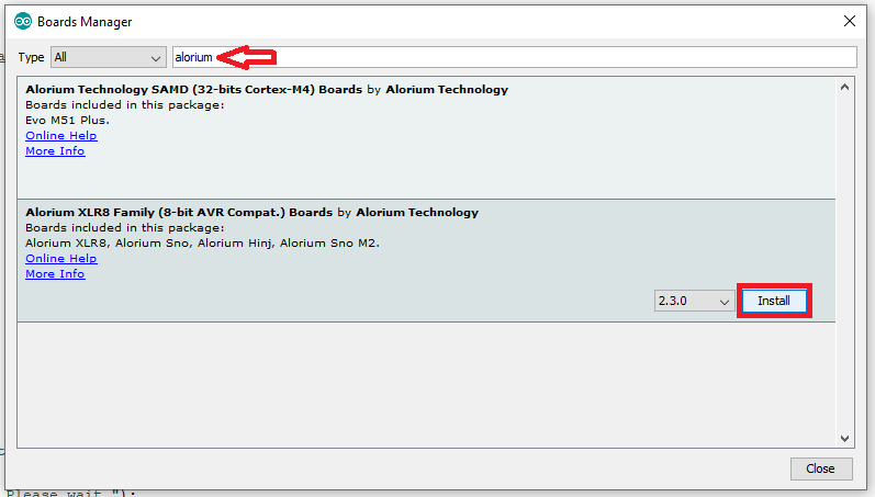
Start by going to Tools > Board > Boards Manager. Type “Alorium,” in the search field and you will see an option to install board files for Alorium Arduino compatible boards. Select the “Alorium XLR8 Boards” package and then click “Install”.
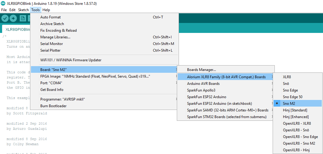
Go to Tools > Board. You should see that a new section titled “Alorium XLR8 Family” now exists. Under this new heading should be the Sno M2 board. You can select the "Sno M2" board just like you would normally select the “Arduino/Genuino Uno” board.
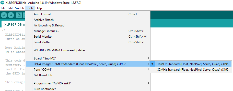
After selecting the Sno M2, you will find a new menu item at Tools > FPGA Image, where you will find a number of FPGA images that provide different operating speeds and different XB configurations.
Installing the XLR8 board support will also install a default set of libraries that are needed to take advantage of the extra capabilities of Snō. You can see these libraries listed in the Sketch > Include Library menu.
There are additional libraries available that can be installed using the Library Manager. In the Arduino IDE, go to the menu Sketch > Include Library > Manage Libraries, which will open the Library Manager in a new window. Enter "Alorium" in the search bar and you will find the entries for the various XLR8 and Snō libraries available.
There are many libraries you can install to support a variety of our board functions and Xcelerator Blocks. For the purposes of this getting started guide, find the “XLR8Info” library and click on it.

An Install button will appear for it. Click on the Install button, and when the installation is complete you will see that the library is now tagged as Installed.
After adding the library, you’ll find it in the menu Sketch > Include Library, under Contributed Libraries (You may need to re-start the IDE if you don’t see it).
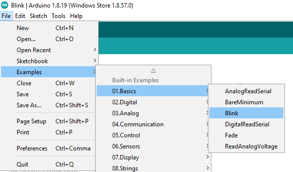
You’ll also find some examples sketches in the File > Examples menu, under the library name.
With the Sno Processor Board inserted into the M.2 slot and secured, plug your ATP board to your computer with a USB cable. Make sure you have the correct Board, FPGA Image, Upload Action, and Port as you see below.
Go to Tools > Board and select the Sno M.2. Then go to File > Examples > 01. Basics and select Blink.
Upload the sketch as you see here:
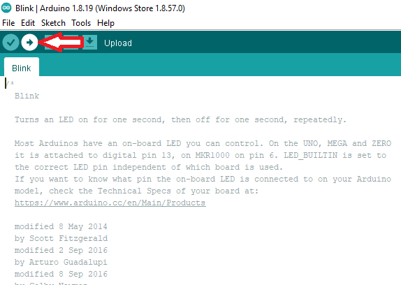
If all goes well, you should see something like the gif below:
To run with the XLR8Info XB and library, do the following:
Connect Snō to your computer with a USB cable, and set up the Port and Serial Monitor as you normally would. Go to Tools > Port and verify that Arduino IDE is connected to the XLR8 USB serial port.
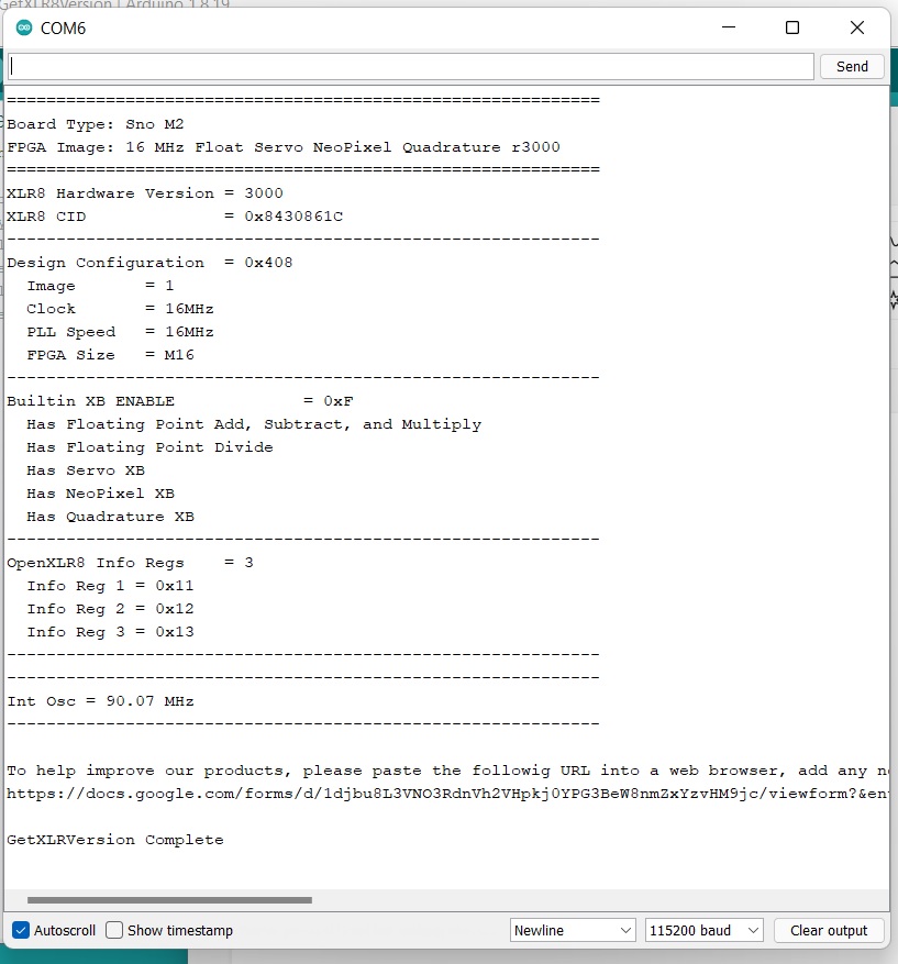
Go to Tools > Board and select the XLR8 board. Then go to File > Examples > XLR8Info and select "GetXLR8Version".

In the GetXLR8Version sketch window, click on the Upload button
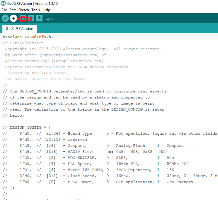
Check the Serial Monitor window for the output, which should look like the output below. Note that you will need to set the baud rate for the Serial Monitor to 115200 for this sketch to display output correctly.
For more information, check out the resources below:
For more information about the SparkFun MicroMod Ecosystem, take a look at the links below:
Need some inspiration for a project using your Alorium Sno Processor? The tutorials below may help you get started!
learn.sparkfun.com | CC BY-SA 3.0 | SparkFun Electronics | Niwot, Colorado