micro:bit Educator Lab Pack Experiment Guide
Experiment 3: Using a Buzzer
Introduction
In this experiment, we will again bridge the gap between the digital world and the analog world. We'll be using a piezo buzzer that makes a small "click" when you apply voltage to it (try it!). By itself that isn't terribly exciting, but if you turn the voltage on and off hundreds of times a second, the piezo buzzer will produce a tone. And if you string a bunch of tones together, you've got music! This circuit and set of code blocks will create a simple sound machine.
Parts Needed
You will need the following parts:
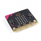
- 1x micro:bit
- 1x micro-B USB Cable
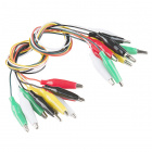
- 2x Alligator Leads
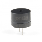
- 1x Piezo Buzzer

Introducing the Piezo Buzzer
The buzzer is a small component with a piece of metal in it that moves when you apply a voltage across it. This motion causes a small sound, or "click."

If you turn the voltage on and off fast enough, you get different beeps, squeals, chirps and buzzes. You can use PWM to control the speed of turning the piezo on and off --- and, in turn, the audio frequency coming out of the buzzer. Adjusting the PWM enables you to get legitimate notes out of the buzzer.
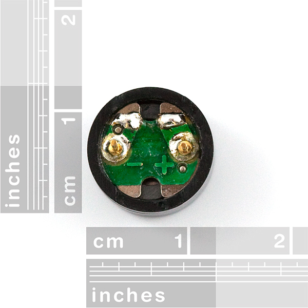
If you received one in the previous lab pack, you can flip the buzzer over and look at the bottom. You will see that one pin has a (+) next to it. That pin gets connected to a signal from the P0 pin. The other pin should be connected to ground.
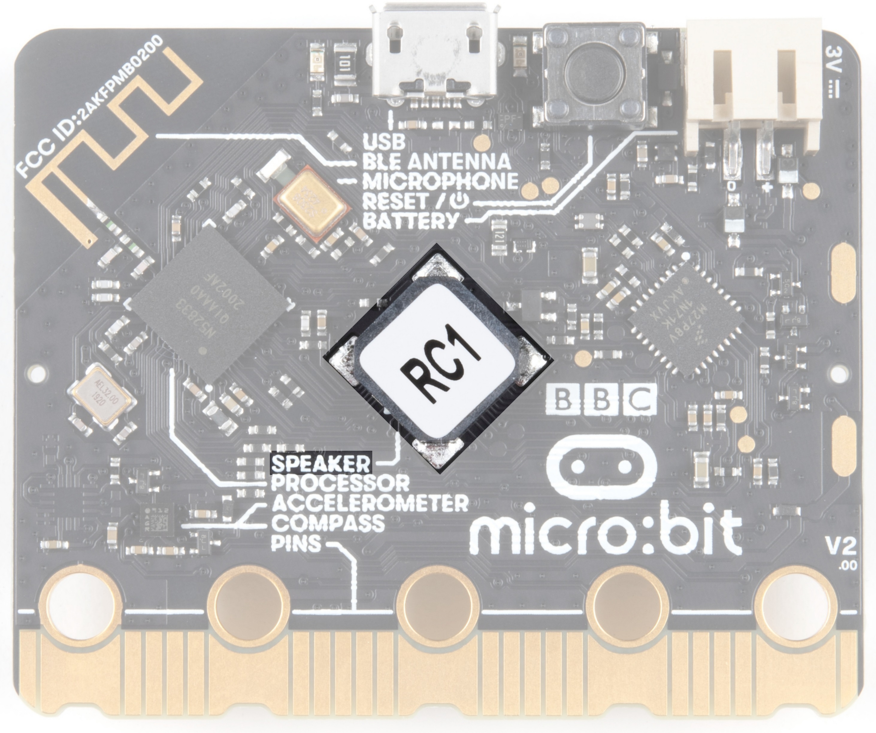
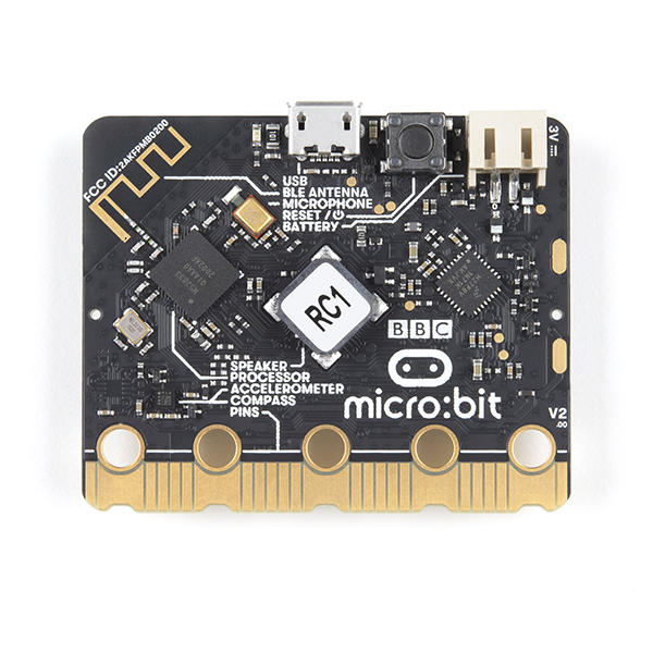
For users with micro:bit v2, there is a built-in piezo buzzer on the back of the board. If the sticker is removed, you will notice a polarity sign (e.g. "+") on the component as well.
Hardware Hookup
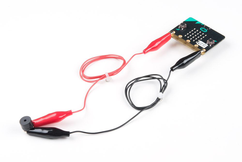
Ready to start hooking everything up? Check out the wiring diagram below to see how everything is connected.
| Polarized Components | Pay special attention to the component’s markings indicating how to connect it to the micro:bit. Polarized components can only be connected to a circuit in one direction. |
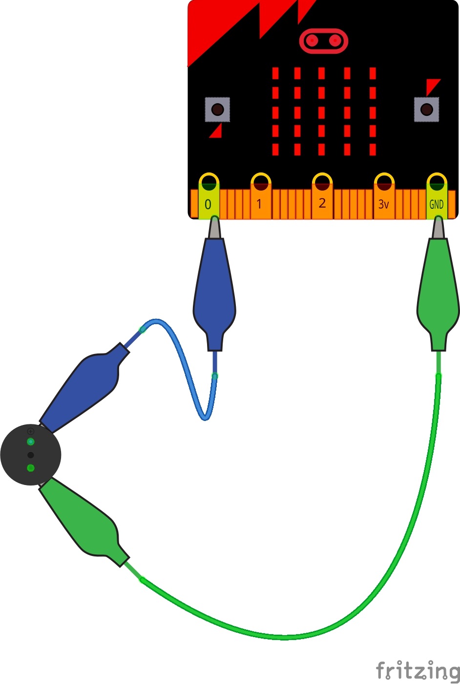
Wiring Diagram for the Experiment
For users wiring an external piezo buzzer with micro:bit V1, you would follow the diagram below.
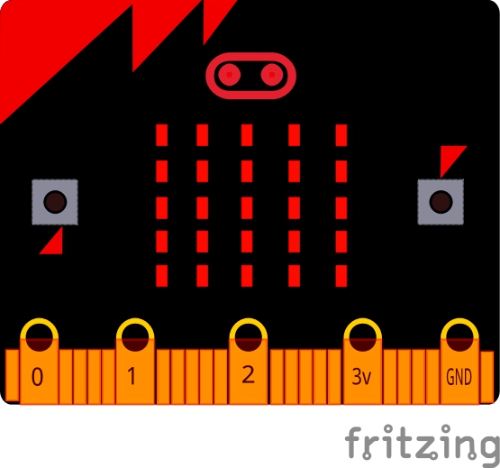
For users with the micro:bit V2, you do not need to connect anything for this example since it has a built-in piezo buzzer! You will just need to define the output in code.
Run Your Script
Either copy and paste, or re-create the following code into your own MakeCode editor by clicking the open icon in the upper right-hand corner of the editor window. You can also just download this example by clicking the download button in the lower right-hand corner of the code window.
For users with micro:bit V1, simply remove the
set built-in speaker code block before compiling and downloading the program in the editor. Of course, you can head back to the old code as well. Code to Note
Let's take a look at the code blocks in this experiment.
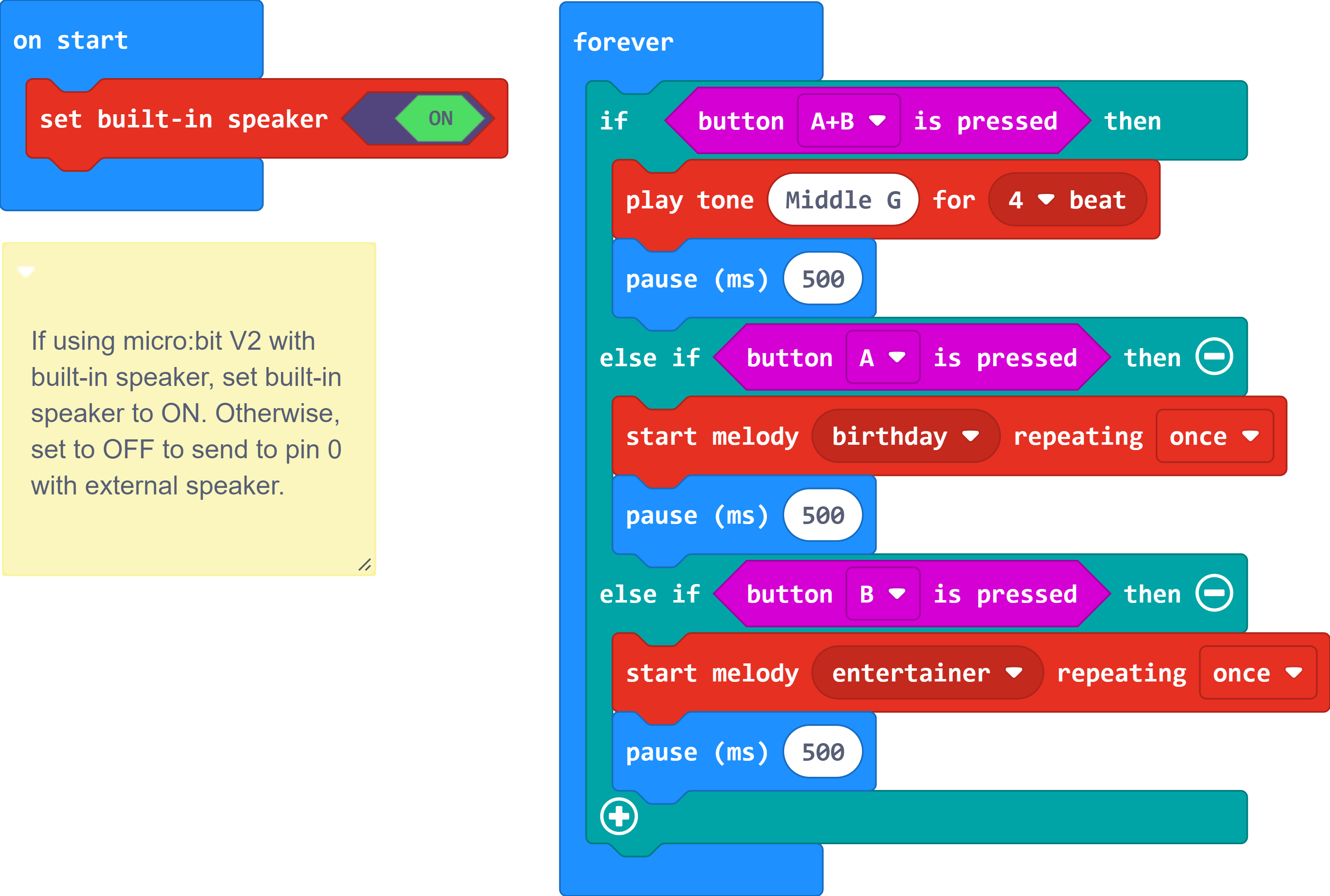
Set Built-in Speaker
The set built-in speaker sets the output for the speaker. By default, this outputs to the built-in speaker on micro:bit v2. Setting it to OFF will output the signal to an external piezo buzzer on pin 0.
Button Pressed
The button pressed block checks the on-board buttons of the micro:bit and allows you to add logic based on whether or not those buttons are pressed.
Play Tone for
The play tone for block is pretty standard if you are used to making sound with other microcontrollers. For example, tone() function in Arduino is pretty much the same as this block. The play tone for block accepts a note that you would like the buzzer to produce and the length of time in beats per second that you would like it to play. So if you are a musician, you are golden to write horrible robot music for your friends!
Start Melody Repeating
The Start Melody Repeating block takes all of the frustration out of getting music out of a microcontroller. It is as simple as selecting one of a number of songs that are preprogrammed into MakeCode and how many times you want it to repeat and you are done! Note that when a melody is playing no other code can run, this is called "blocking" code and has to be accounted for you in your program.
What You Should See
What you should see --- well, nothing! What you should hear --- a song should start as soon as the program starts to run on your micro:bit V1 and a button is pressed! Each button has its own song, and there's another song if you press both buttons at the same time. Enjoy your sound machine and feel free to swap out the song of your choice!
For users with a micro:bit v2, you will hear sound from the built-in speaker once a button is pressed.
Troubleshooting
No Sound
Given the size and shape of the piezo buzzer, it is easy to miss the right holes on the breadboard for users connecting an external piezo buzzer. Try double-checking its placement. Also, make sure that the set built-in speaker is set to the correct position. When using an external piezo buzzer, it must be set to the OFF position. Users with micro:bit v1 will need to delete the code block. Users with micro:bit v2 will neet to set built-in speaker to the ON position.
Feeling Let Down and Deserted
Create your own song using just the tone blocks rather than the standard song options given from the start melody block.