LTC4150 Coulomb Counter Hookup Guide
 MikeGrusin
Running the Example Code
We've included two example programs for the Arduino microcontroller to show you how to use the Coulomb Counter. If you're not using an Arduino, the example code is very straightforward and should be easily adapted to other microcontrollers.
To Interrupt or Not to Interrupt?
The two code examples are called "Coulomb_int" and "Coulomb_polling". They do exactly the same thing (measure battery consumption), but differ in the way they detect changes on the INT output. Which one you choose will depend on your requirements and skill level.
Interrupts
The "standard" way to detect a pin change is to use interrupts. Interrupts are a hardware feature built into microcontrollers that allow them to handle high-priority events immediately.
To use interrupts, you write a special function called an Interrupt Service Routine (ISR) and set up the hardware appropriately. Then whenever a special interrupt pin on your microcontroller receives the desired input (goes high or goes low), whatever is going on in the main loop is paused, and your ISR function runs. When the ISR function finishes, the main loop picks up right where it left off. This all happens automatically - the only way the main loop would know that anything had happened would be if the ISR function changed some variables behind the scenes (such as how much battery is left, which is exactly what we do in the example code).
The interrupt example code has the advantage of not needing the CLR input, so you can get away with only two I/O pins; INT and POL.
Note that on ATmega 368-based Arduinos, only two pins support external interrupts without additional libraries: D2 (INT0) and D3 (INT1). We use D3 in our example code.
Polling
Interrupts are very useful, but if you're still learning the finer points of programming, there's no shame in using a simpler technique called polling. Polling is simply testing an input over and over again until it becomes the state you're looking for.
By default, the Coulomb Counter is set up so that the INT output will go low and immediately return high. It will only be low for a few microseconds (millionths of a second!), which is enough for interrupt-based code to detect the falling edge, but random checking will almost certainly miss such a brief signal.
However, if you open (clear) solder jumper SJ1, each time INT goes low, it will stay low until you manually reset it. This makes it much easier to write polling code, as INT will stay low until the next time you get around to checking it. To reset it, make CLR low and then high.
The polling example code has the disadvantage of requiring three I/O pins as opposed to two (INT, CLR, and POL). You should also be careful to ensure that you check INT faster than every half-second or so; if a new INT comes in while the old one is still low, you will miss it.
Wiring the Hardware
Here are the minimum required connections for the example sketches. (See the previous page for wiring diagrams.)
If you want to try the interrupt example code:
- Leave solder jumper SJ1 closed (the default)
- You will need to connect (at least):
- VIO to VCC
- INT to D3
- POL to D4
- GND to GND
If you want to try the polling example code:
- Open (clear) solder jumper SJ1 (Instructions)
- You will need to connect (at least):
- VIO to VCC
- INT to D3
- POL to D4
- GND to GND
- CLR to D6
For EITHER version of the code:
- Ensure that SJ2 and SJ3 are both open (clear) for a 5V Arduino, or both closed (soldered) for a 3.3V Arduino.
Downloading the code
The example code is maintained at the Coulomb Counter BOB Github repository. You can download a ZIP file of the entire repository (or clone it to your computer if you have the github software installed), or save the sketches directly:
For either version of the code, you should change line 120 to reflect the full capacity of your lipo battery. The default is 2000mAh:
volatile double battery_mAh = 2000.0; // milliamp-hours (mAh)
This will provide an accurate readout of how many mAh remain in your battery as you use it.
Running the Example Code
Upload the code to your Arduino as you normally would. Open a serial monitor window set to 9600 baud. You should see a reset message, followed by updates as INT "ticks" occur.
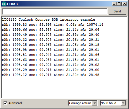
The columns from left to right are:
- mAh (milliamp-hours) remaining in the battery (subtracted from the battery size value at line 120)
- State-of-charge (percentage remaining)
- Time delay between ticks
- Average mA computed from the last time delay.
Note that the first mA reading will be incorrect, as it requires the time delay between two readings to perform its calculations.
Remember that if you don't have anything connected to the output of the Coulomb Counter, the current passing through the board will be zero and you will not see pulses from the INT pin. (You may get one pulse every 10 minutes or so from the very small amount of current that the LTC4150 chip uses.)