LTC4150 Coulomb Counter Hookup Guide
 MikeGrusin
 Connecting the Hardware
The LTC4150 Coulomb Counter IC has a very simple interface. It has an INT (interrupt) output that is normally high, but will go low when a given amount of current has passed through the device. There is also a POL output that tells you which direction current is flowing.
Max Ratings
The Coulomb Counter can accommodate power sources up to 8.5V, and currents up to 1A. It works particularly well for single-cell (3.7V) Lipo batteries.
On the interface side, the Coulomb Counter can be attached to systems running at either 3.3V or 5V (see solder jumpers below). The resistors on the board have been selected for those two voltages; other I/O voltages may need different resistor values.
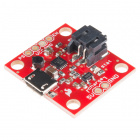
Solder jumpers
There are three solder jumpers on the Coulomb Counter board that configure it for different situations. Please read this section carefully and make any necessary changes before using your Coulomb Counter.
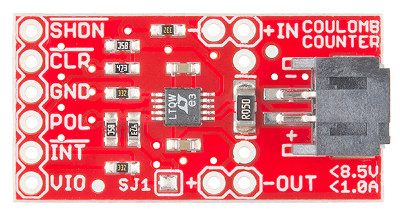
- Solder jumper SJ1 (on the component side of the board) controls the behavior of the INT output. If SJ1 is closed (the default), INT will pulse low and immediately return high. If SJ1 is open (clear), INT will stay low until you use the CLR input to manually reset it. If your code uses interrupts to detect INT ticks, you will probably want to leave SJ1 closed. This will save you the step of having to manually reset INT on each tick. If you are manually polling the INT output, you will probably want to open (clear) SJ1 to give you more time to detect the low signal. See the Example Code section for more information on interrupts vs. polling.
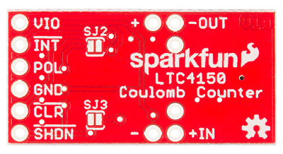
- Solder jumpers SJ2 and SJ3 (on the bottom of the board) select whether you'll be connecting the Coulomb Counter to a 3.3V or a 5V system. If you're using a 5V system (the default), leave these two solder jumpers open (clear). If you will be connecting the Coulomb Counter to a 3.3V system, close both of these jumpers.
To close a solder jumper, melt a small blob of solder onto the jumper so that it bridges both pads, shorting them together.
To open or "clear" a solder jumper, use some solder wick and a hot iron to remove the solder blob bridging the two pads. Place the wick over the blob, and heat the blob through the wick. When the solder melts, the wick will absorb it. When you're done, ensure that the two pads are fully separated (no solder bridging them).
Electrical Connections
As you would when using an ammeter, you will need to install your Coulomb Counter between your power source (usually a battery) and your circuit. All the current your circuit uses needs to pass through the Coulomb Counter to be measured.
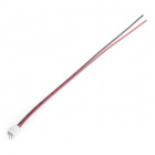
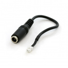
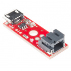
At one end of the breakout board are headers labeled IN and OUT. Connect your battery or power supply to the IN header or JST battery connector (they're identical), and connect the OUT header to your project. The JST connector matches the connectors used on SparkFun Lipo batteries, and can be used to connect a single-cell 3.7V Lipo battery as your power source. (You could also add a 2-pin JST pigtail or adapter to your own battery or other power source and plug it into this connector).
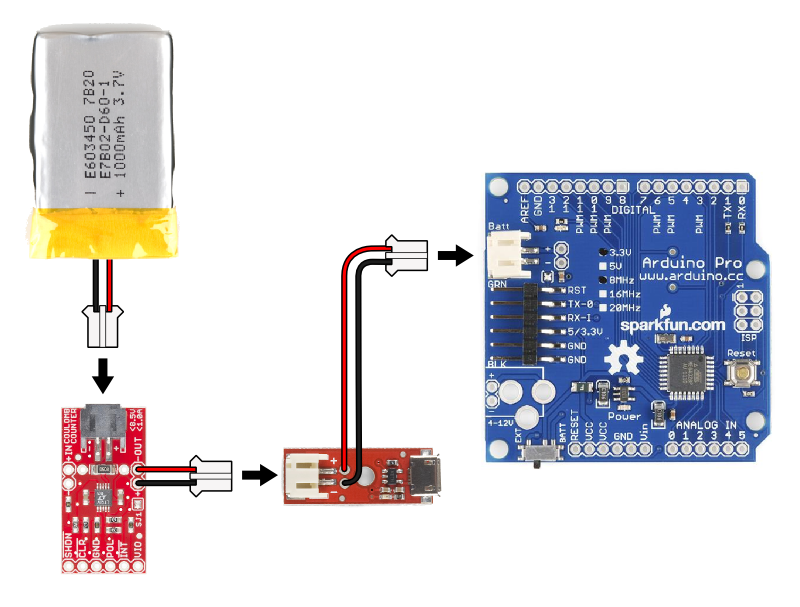
Note that if you'll be using both the Coulomb Counter and a Lipo charger, connect the Coulomb Counter (not the charger) directly to your battery. This way the Coulomb Counter can monitor both charging and discharging:

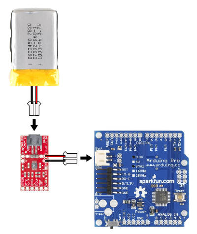
PROTIP: if you connect a JST pigtail to the output of the Coulomb Counter, you can conveniently plug it straight into your system's JST battery connector:
You can even do the same thing to a Lipo charger, for complete plug-and-play modularity:
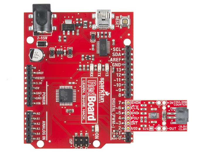
Interface pins
At the other end of the Coulomb Counter, you'll find a header with six pins. These are the pins you'll need to connect to your microcontroller. Depending on what you want to do, you'll need at least the first four pins:
| Name | Function | Direction | Notes |
| VIO | I/O Voltage | Power | Connect to 3.3V or 5V depending on your system. Note that you may need to change jumper settings (see above). |
INT |
Interrupt | Output (from CC) |
Goes low when 0.0001707 amp-hours have passed through the board. Is cleared (goes high) when CLR goes low. Connect to an interrupt input pin. |
| POL | Polarity | Output (from CC) |
Indicates direction of current flow. Low = current from IN to OUT (discharging). High = current from OUT to IN (charging). |
| GND | Ground | Power | Connect to GND pin on your system. |
| CLR | Clear | Input (to CC) |
If INT is low, make CLR low to reset INT. This is done automatically if SJ1 is closed (ties CLR and INT together). This pin can be left disconnected if SJ1 is closed and you are using interrupts to sample INT. |
| SHDN | Shutdown | Input (to CC) |
If SHDN is low, the chip will be held in reset. There is a pullup resistor from this pin to VIO, so if you leave it disconnected, the board will remain active. This pin can be left disconnected if you do not need the shutdown function. |
<
p>
PROTIP: When you see a signal name that contains an asterisk or has a line over it, that's an indication that this signal uses "negative logic". In negative logic, a low logic level means the signal is asserted or active. Thus, if you see a signal named RESET, you must provide a low signal to reset the part, and keep it high at other times.
Note that the Coulomb Counter is powered by the IN header (usually your battery) and not by the VIO pin, which is used only as a voltage reference for the output pins. This is so that the small amount of power used by the Coulomb Counter itself is included in its measurements for maximum accuracy. The Coulomb Counter uses under 1mA when it's running, and you can use the SHDN (shutdown) input to reduce its power consumption further (though it will not be able to keep track of current use while shut down).
Typical Connections
Before plugging your Coulomb Counter into your microcontroller, see the Solder Jumpers section above for instructions on setting up the board for a 3.3V or a 5V system.
Our Arduino Example Code has been written so that you can plug the Coulumb Counter board directly into Arduino digital pins 2 through 7 as shown below. (We've made D2 permanently HIGH for VIO, and D5 LOW for GND.)
This makes it easy to test out the board, but in most cases you will want to use wires to connect the boards so as not to waste valuable I/O ports on pins that could be left disconnected. Speaking of which:
Do I need to use all six pins?
Probably not!
If you will be using interrupts to sample the INT signal (recommended), you can leave the CLR pin disconnected.
If you do not need shutdown functionality, you can leave the SHDN pin disconnected.
You can connect VIO and GND to your system's regulated voltage (3.3V or 5V) and GND. You don't need to waste I/O pins.
If you're using interrupts to sample the INT signal (recommended), you can get away with only two I/O ports (INT and POL) plus VIO and GND. Note that for ATmega 328-based Arduinos, INT can only be connected to D2 or D3 without additional pin-change-interrupt libraries.
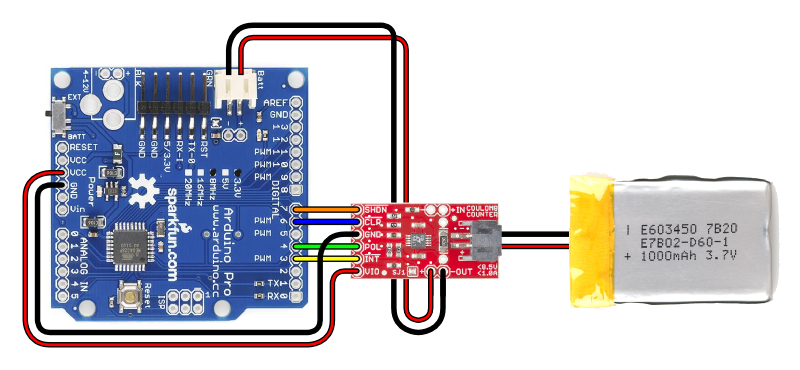
3.3V Systems
The Coulomb Counter is well-suited for 3.3V systems like the Arduino Pro or Pro Mini:
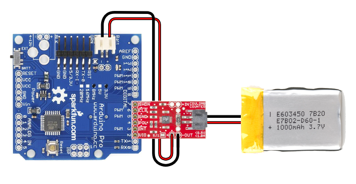
These diagrams show the use of a single-cell Lipo battery powering the system. Note that you should also connect 3.3V to VIO and GND to GND for the logic level reference. You can do this with the Arduino's VCC (3.3V) line, or connect it to an I/O pin set HIGH as we do in our Example Code.
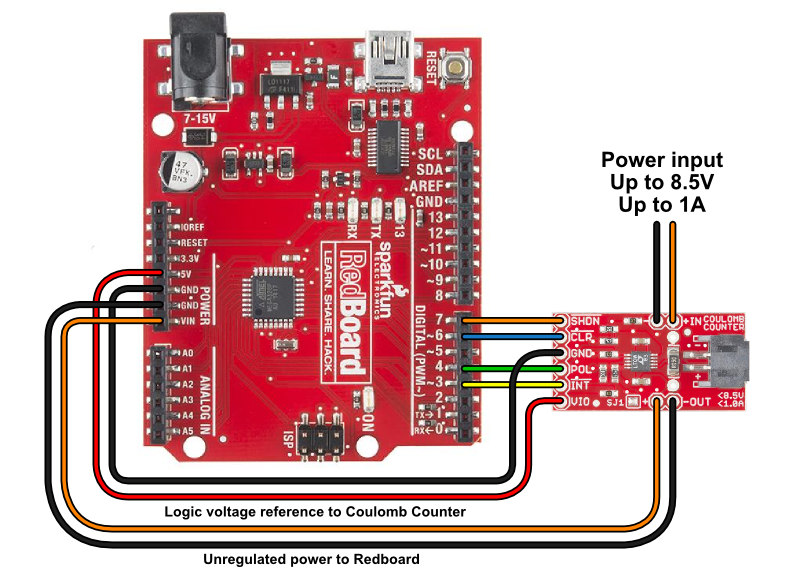
5V Systems
For 5V systems like the Arduino Uno or SparkFun Redboard, you can run an unregulated supply up to 8.5V through the Coulomb Counter to the Arduino's VIN terminal. Note that you will need to connect 5V to VIO for the logic level reference. You can do this with the Arduino's 5V line, or connect it to an I/O pin set HIGH as we do in our Example Code.
If you want to power the Arduino from a regulated 5V line, you can do that as well. Run the power supply through the Coulomb Counter to the Arduino's 5V terminal. You will also need to get 5V to the Coulomb Counter's VIO pin, and so on.
