$11.50
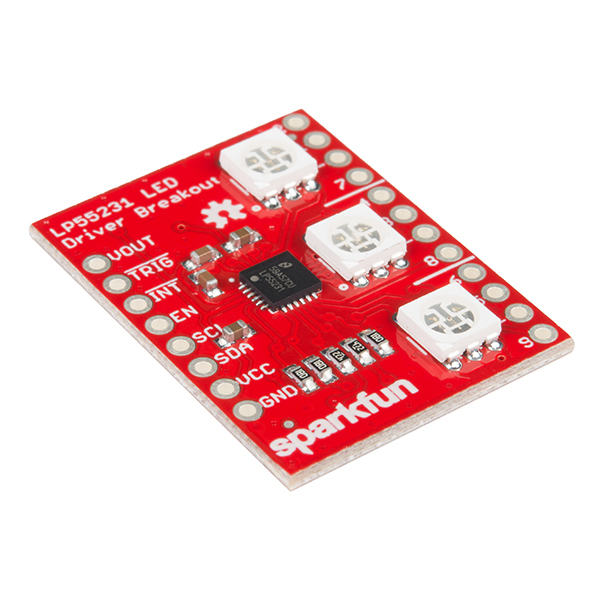
The SparkFun LP55231 Breakout Board features Texas Instrument's LP55231, a nine-channel, I2C LED controller. It drives LEDs using pulse-width-modulation, so it is well-suited for variable intensity and color mixing applications.
It's intended for mobile device and automotive applications, offloading LED control operations from a host controller. It's not meant to be blindingly bright, but it's got a couple useful tricks up its sleeve.
The breakout board includes the chip, and adds three RGB LEDs, plus connection pads and configuration jumpers.
In this hookup guide, we'll demonstrate the difference between the regular and offloaded modes. We'll start with a simple application to illustrate using the LED driver under control of the host microcontroller, then move on to show the capabilities of the offload engines. The second example will be much more technical and will put your programming chops to the test.
Before embarking upon this guide, you may want to familiarize with any of the topics below.
The LP55231 Breakout is a self-contained solution for developing and deploying the LP55231. It includes the LP55231 LED controller IC, plus three RGB LEDs. It also sports pads and jumpers for replacing the onboard LEDs with external ones, and configuring the I2C bus, which allows you to daisy-chain up to four LP55231's.
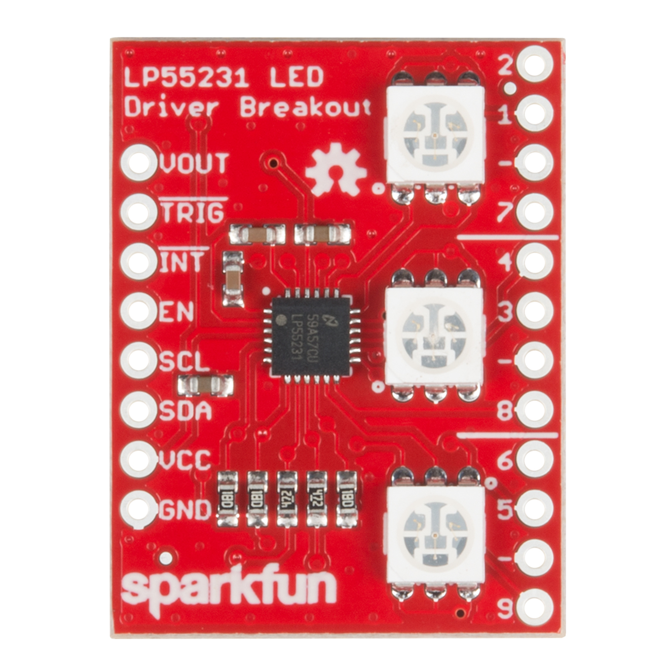
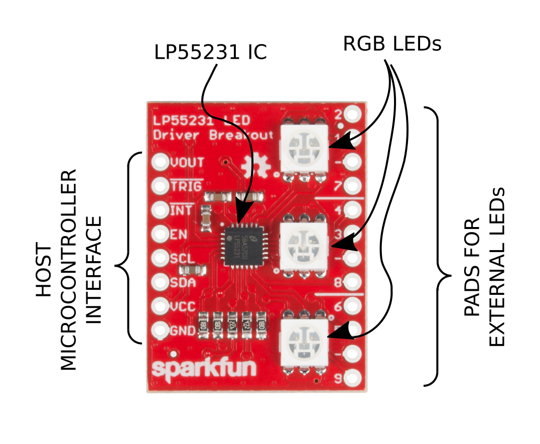
Along the left edge if the board are the logic signals that interface with the host microcontroller. This is the power input (GND and VCC pads), the I2C bus (SDA and SCL), and logic signals to interact with the execution engines (TRIG and INT). Finally, the charge pump voltage is available on the VOUT pad.
Towards the center of the board is the LP55231 chip, with supporting components. The chip is mostly self contained, though it requires a few resistors and capacitors.
The board has three WS2801 RGB LEDs on it.
Adjacent to the RGB LEDs are groups of four pads, for attaching external LEDs. The pads are in the same order as a common-cathode PTH LED, though, with some creativity, you can apply other LEDs.
Because the outputs are current sources, you don't need a series resistor when attaching external LEDs. Instead of calculating a resistor value for bias current, the current is configured by writing registers in the LP55231.
While the breakout is functional with no further configuration, it can be tailored to specific applications using solder jumpers on the back of the board.
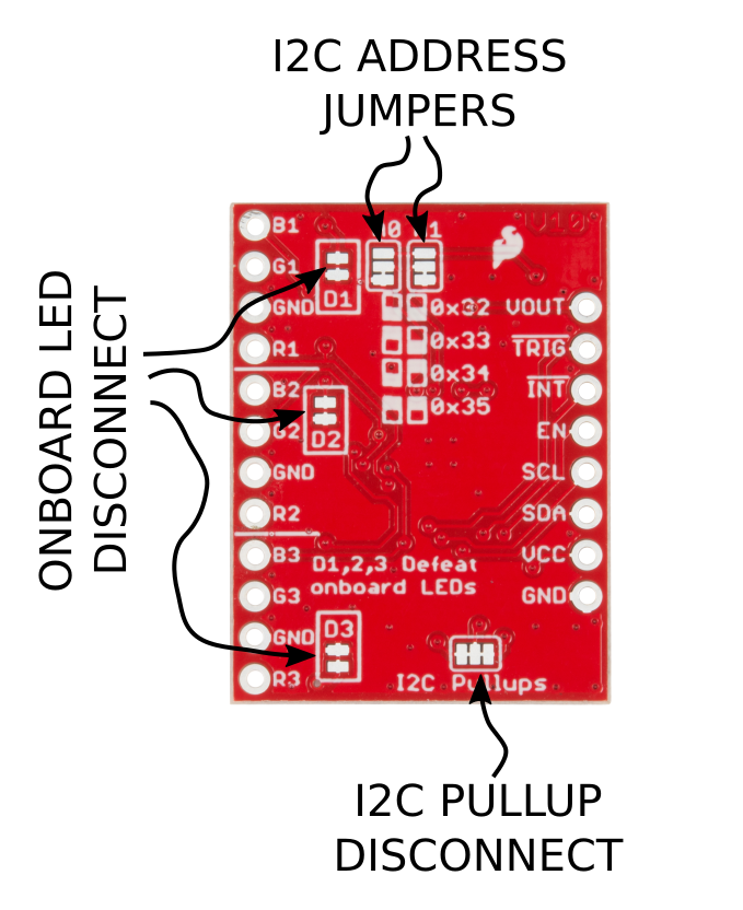
As mentioned above, the breakout includes RGB LEDs, with pads for adding external LEDs. If you're adding external LEDs, you can defeat the onboard RGBs by cutting jumpers D1, D2 and D3.
If you want to daisy-chain more than one LP55231 breakout, you'll want to assign each board a unique I2C address. You'll also want to defeat the I2C pullup resistors on all but one board, usually the last one in the chain.

For an apparently tiny chip that simply illuminates LEDs, the LP55231 has a lot inside. Before we get into the example projects, lets take a peek under the hood.
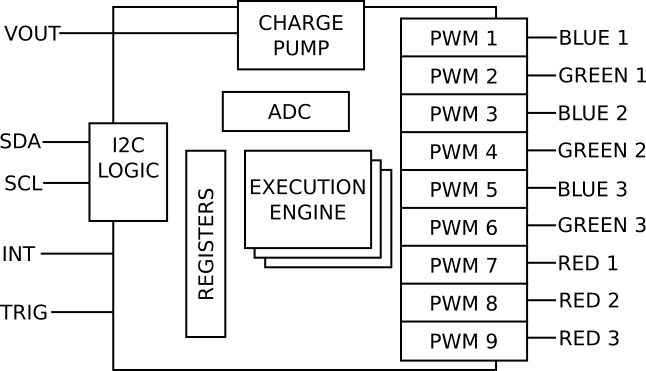
The chip has 118 registers on the I2C bus, divided into several sections.
The charge pump is a power supply that boosts the input voltage to a higher level.
Green, blue and white LEDs all have forward voltages in the 3.4VDC range. On a system powered from a 3.3V supply, they won't light up, so the LP55231 uses the charge pump to create a higher voltage to get those LEDs to turn on.
The charge pump is only used for the first six outputs -- the other three all use the system voltage. Channels 7, 8 and 9 are intended to drive red LEDs, which have a forward voltage around 2 volts, so they have no problem operating from a 3.3V supply. This also means that when driving RGB LEDs, the red, green, and blue channels aren't adjacent.
The IC enables the charge pump automatically when it detects that the system voltage is in the 3.3V range. With a 5V power supply, the charge pump is bypassed, and the 5V supply is used for all LEDs.
The LED output drivers are Pulse Width Modulation outputs. They are highly configurable, with many options determining how they drive the outputs.
First, they are current-source outputs, configurable to match the attached LEDs, to a maximum of 25.5 mA per output. The output current is set per-channel by writing the corresponding current control registers.
Each output can also be configured to a logarithmic brightness response curve. Our eyes preceive light on a logarithmic scale, so the log mode allows the chip to fade in and fade out in a more visibly obvious manner. The tradeoff is that log mode doesn't achieve the brightest overall response.
Outputs can be grouped together using master fader channels. By assigning outputs to a master fader, the host microcontroller can control many LEDs with a single write operation. Master faders are also useful for fading mixed colors. The intensity of a mixed color can be controlled, without causing the color to shift as it fades.
The crowning features of the LP55231 are the three execution engines. These are simple computers that perform LED-specific operations. They can set outputs to specific values, perform timed operations like blink and fade sequences, and respond to logic signals.
The engines are programmed using a simple machine language, which is loaded into memory over I2C.
The execution engines are powerful, but also cryptic. We'll demonstrate a program in the Execution Engine example, and there are demonstrations of more advanced features in the GitHub Repository.
The notable thing the LP55231 is lacking is non-volatile storage -- it doesn't have ROM or FLASH memory that would allow it to remember what it was doing across a power-cycle. As such, it works best as a peripheral to a microcontroller, rather than as a stand-alone device.
Before we get into some software examples that use the LP55231 breakout, we'll need to connect it to a microcontroller. The examples were written using a 3.3V Pro Micro, but any Arduino-compatible microcontroller with an I2C interface will work with a little translation.
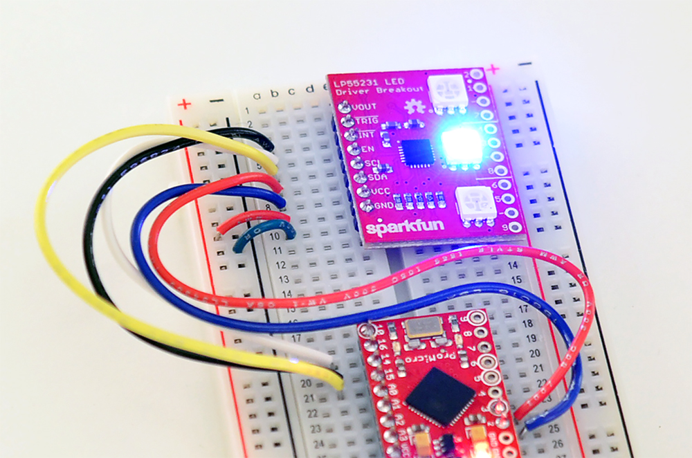
There's not much to the circuit: the Pro Micro, the LP55231 breakout, and a few wires to connect them.
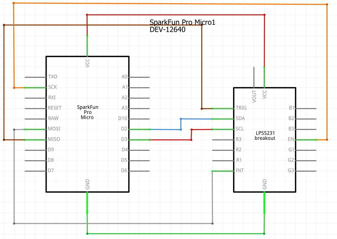
The connections are relatively simple. For simple operations, you'll need to connect 5 wires from the microcontroller to the LP55231. For some of the more sophisticated examples, you'll also need to connect two GPIO pins for INT and TRIG.
| Pro Micro Pin | LP55231 Pin |
|---|---|
| GND | GND |
| VCC | VCC |
| GPIO 2 | SDA |
| GPIO 3 | SCL |
| GPIO 15 | EN |
| GPIO 16 | INT |
| GPIO 14 | TRIG |
The Fritzing layout looks like this
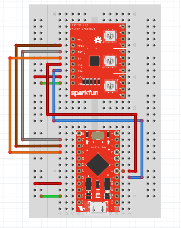
Which was built on a breadboard as shown below.
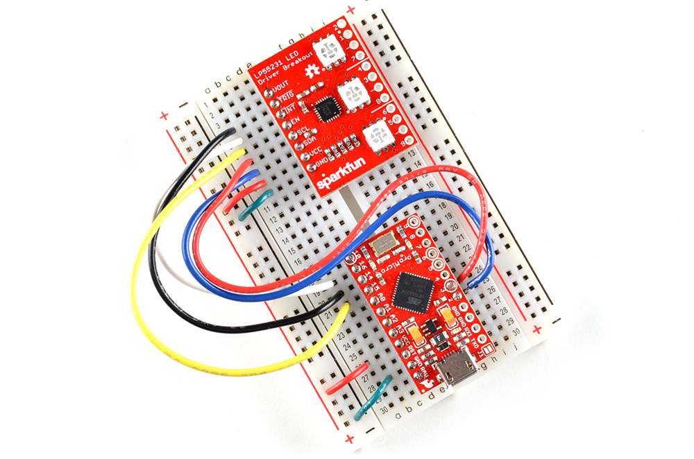
Since we'll be using Arduino to load the example sketches, we can use the USB connection to power to breadboard. If you want to disconnect USB and use another source of power, you can connect a source of regulated 3.3VDC to the VCC connection, or a source of up to 16VDC to the RAW pin on the Pro Micro.
We've written an Arduino library to control the LP55231. It consists of two classes, which allow different degrees of control over the IC.
Lp55231 class provides simple LED control.Lp55231Engines class extends the Lp55231 class, adding more sophisticated LP55231 features, such as the execution engines, and internal diagnostics, though also consuming more flash memory to do it.We'll explore both classes in the following examples.
We'll start with a simple example: initializing the IC, and turning the LED channels on and off.
language:c
/******************************************************************************
simple-demo.ino
simple demo of using LP55231 to control 9 LEDs.
Byron Jacquot @ SparkFun Electronics
October 12, 2016
https://github.com/sparkfun/SparkFun_LP55231_Arduino_Library

The simplest demo of LP55231 functionality.  Initializes the chip, then
sequentially turn on each of the 9 channels.

Resources:

Development environment specifics:
Written using Arduino 1.6.5

This code is released under the [MIT License](http://opensource.org/licenses/MIT).

Please review the LICENSE.md file included with this example. If you have any questions
or concerns with licensing, please contact techsupport@sparkfun.com.

Distributed as-is; no warranty is given.
******************************************************************************/

#include <Wire.h>
#include <lp55231.h>

Lp55231 ledChip;

void setup() {
// put your setup code here, to run once:

    Serial.begin(9600);
    delay(5000);
    Serial.println("-- Starting Setup() --");

    ledChip.Begin();
    ledChip.Enable();

    delay(500);

    Serial.println("-- Setup() Complete --");
}

void loop() {
// put your main code here, to run repeatedly:

// current will track the LED we're turning on
// previous will keep track of the last one we turned on to turn it off again

    static uint8_t current = 0, previous = 0;
    static uint32_t next = millis()+1000;

    if(millis() >= next)
    {
        next += 1000;

        Serial.print("Illuminating: ");
        Serial.println(current);

        ledChip.SetChannelPWM(previous, 0);
        ledChip.SetChannelPWM(current, 255);

        previous = current;
        current++;
        if(current >= ledChip.NumChannels)
        {
            current = 0;
        }
    }
}
The Lp55231 class is declared with no parameters, initializing it to the default I2C address of 0x32. Begin initializes the I2C bus, and Enable turns on the LED driver stages.
As loop runs, it cycles among the outputs, calling SetChannnelPWM on each channel in turn, to turn it on, wait for a moment, then turn it off and proceeed to the next channel.
The result of the program is that each LED lights successively: blue one, green one, blue two, green two, blue three, green there, then each of the red channels.
There are a couple other demos of the simple Lp55231 library in the repository.
SetChannelPWM methods, and also assigned to the same master fader using AssignChannelToMasterFader. As loop executes, it adjusts the group using SetMasterFader. The color ratios established in setup are maintained as the master fader value is adjusted.The most interesting features in the LP55231 are the three execution engines. These are three simple, independent, computers that can be programmed to perform LED-related tasks. Before we can look at code written to run on them, we need a little more complete concept of what's inside and how it works.
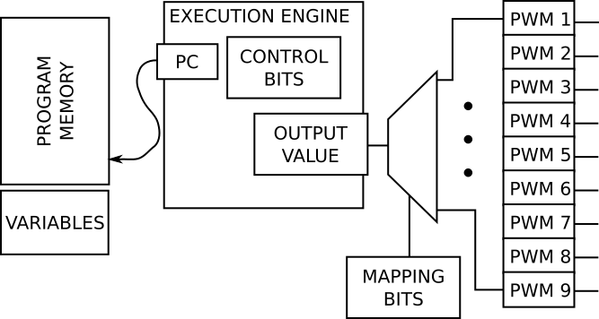
Each engine has the following structure:
Each engine is a simple Fetch-Execute Machine. A Fetch-Execute Machine is the basis for a computer. When we think of a computer, we usually think of a general-purpose machine that can be programmed to accomplish many different tasks, such as writing documents or performing mathematical work. In contrast, this one is tailored to LED-specific tasks.
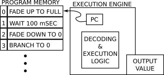
It works like this:
For example, when the program in the diagram above starts, the PC is pointing at location 0, so the engine fetches the instruction FADE UP TO FULL. The engine would increment the output value until it reaches maximum, then increment the PC and fetch the next instruction.
The 96 words of program memory mentioned above store a program, which is a series of encoded commands, or Instructions. Within the 16-bit words, some bits describe the action to be taken, while others modify that action, specifying things like brightness levels, channel mapping and ramp times.
The LP55231 instruction set is broken into four categories.
This group of instructions effects the LED output of the engine. The output can be set directly, instructed to ramp from one value to another, or simply pause for a specified time.
Each engine calculates a single output value. The engine output can be routed to a single LED with the MUX_SEL instruction.
The mapping instructions can also send that value to multiple outputs, using an indirection table. The table contains one or more bitmaps that describe the outputs controlled by the engine -- the LSB maps to output 1, the next bit to output 2, and so on, using 9 bits. The program uses instructions to select the outputs by referencing the table entries.
A table can be composed of multiple entries, and output selections sequenced by selecting new rows in the table. We'll show how to use this in the following example.
Ordinarily, as the program executes, the PC increments to select the next instruction. The BRANCH instructions change this behavior.
Branches cause the program counter to be loaded with a new value, to create loops and conditional execution (like for or if statements).
The Interrupt instruction allows the LP55231 to notify the microcontroller that it has reached a specified line in the program. The Trigger instruction makes the engine wait until certain conditions (such as a logic level on the Trig input) are present.
There are also RST and END instructions. Reset causes the program to start over form the beginning, while End causes the engine to halt.
Finally, the LP55231 can perform addition and subtraction on values stored in the variables.
A detailed description of every instruction is in section 7.6 of the LP55231 datasheet.
Now that we have a conceptual model of the execution engines, let's move on to an example that applies them.
To demonstrate the power of the execution engines, we're going to use a classic LED-switching application: the LED scanner.
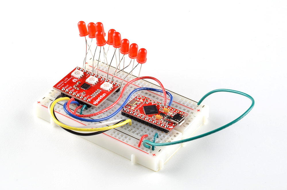
While chasing among the colors of the RGB LEDs is colorful, it doesn't lend the sense of motion that we'd expect from an LED scanner. For a more traditional look, we cut the jumpers to disable the onboard LEDs, and added a group of 9 red 5mm LEDs.
language:c
/******************************************************************************
Engines-scaner.ino
9-channel LED scanner using LP55231.

Byron Jacquot @ SparkFun Electronics
October 21, 2016
https://github.com/sparkfun/SparkFun_LP55231_Arduino_Library

Using output maps for the execution engine, sequentially cycles through the 9
LED outputs, resulting in a scrolling pattern.  See the LP55231 breakout board
hookup guide for a  detailed examination of how this works.

Resources:
Written using SparkFun Pro Micro controller, with LP55231 breakout board.

Development environment specifics:
Written using Arduino 1.6.5

This code is released under the [MIT License](http://opensource.org/licenses/MIT).

Please review the LICENSE.md file included with this example. If you have any questions
or concerns with licensing, please contact techsupport@sparkfun.com.

Distributed as-is; no warranty is given.
******************************************************************************/


#include <Wire.h>

#include <lp55231.h>

static const int32_t enable_pin = 15; // Apparently active high?
static const int32_t trigger_pin = 14; // low if unused
static const int32_t interrupt_pin = 16;

static uint32_t next;

static Lp55231Engines ledChip(0x32);

static const uint16_t program[] =
{
    0x9c10, // 0 map start
    0x9c9f, // 1 map end
    0x06ff, // 2 ramp up
    0x0200, // 3 wait
    0x07ff, // 4 ramp down
    0x9d80, // 5 map next
    0xa002, // 6 loop to 2
    0x000a, // 7 - empty placeholder
    0x0005, // 8 - empty placeholder
    0x000a, // 9 - empty placeholder
    0x0005, // a - empty placeholder
    0x000a, // b - empty placeholder
    0x0005, // c - empty placeholder
    0x000a, // d - empty placeholder
    0x0005, // e - empty placeholder
    0x000a, // f - empty placeholder
    0x0001, // 10 map begin - start of 2nd page
    0x0002, // 11
    0x0040, // 12
    0x0004, // 13
    0x0008, // 14
    0x0080, // 15
    0x0010, // 16
    0x0020, // 17
    0x0100, // 18
    0x0020, // 19
    0x0010, // 1a
    0x0080, // 1b
    0x0008, // 1c
    0x0004, // 1d
    0x0040, // 1e
    0x0002, // 1f  map end
};


void setup()
{
    Serial.begin(9600);

    delay(5000);
    Serial.println("### Setup entry");

    pinMode(enable_pin, OUTPUT);
    digitalWrite(enable_pin, LOW);
    digitalWrite(enable_pin, HIGH);

    ledChip.Begin();
    ledChip.Enable();

    // Chip needs a moment to wake up.

    delay(1000);

    ledChip.ClearInterrupt();

    for(uint8_t i = 0; i < 9; i++)
    {
        ledChip.SetLogBrightness(i, true);
        ledChip.SetDriveCurrent(i, 0xff);
    }

    if(ledChip.LoadProgram(program, (sizeof(program)/2)))
    {
    Serial.println("Program loaded?");

        if(ledChip.VerifyProgram(program, (sizeof(program)/2)))
        {
            Serial.println("program verifies");
        }
    }
    else
    {
        Serial.println("Program dodn't load?");
    }

    next = millis() + 3000;

    ledChip.SetEngineEntryPoint(0, 0);
    ledChip.SetEnginePC(0, 0);

    ledChip.SetEngineModeFree(0);
    ledChip.SetEngineRunning(0);

    Serial.println("### Setup complete");

}

void loop()
{
int32_t result;
int8_t  val;
static uint32_t count = 0;

    if(millis() >= next)
    {
        next += 1000;
        count++;

        Serial.print("# ");
        Serial.println(count);

        Serial.print(ledChip.GetEnginePC(0));
        Serial.print(" ");
        Serial.println(ledChip.GetEngineMode(0));

    }
}
Load the sketch above, and observe that the LEDs chase from side to side.
Let's dissect the sketch a little, and examine a couple of the finer points. We'll read it in reverse, starting at the bottom, and working out way to the top.
First, note what's going on in loop()
language:c
 void loop()
{
    static uint32_t count = 0;

    if(millis() >= next)
    {
        next += 1000;
        count++;

        Serial.print("# ");
        Serial.println(count);

        Serial.print(ledChip.GetEnginePC(0));
        Serial.print(" ");
        Serial.println(ledChip.GetEngineMode(0));
    }
}
It's not doing anything that specifically makes the LED scanner run! It checks the program counter, but doesn't do anything that makes LEDs illuminate. After initialization, all of the LED scanning work is being done independently by the LP55231. This means that the microcontroller is completely available for other tasks.
The tradeoff of avoiding computational load in loop is that the initialization is much more detailed. setup contains the following lines.
language:c
...
ledChip.Begin();
ledChip.Enable();

// Chip needs a moment to wake up.

delay(1000);

ledChip.ClearInterrupt();

for(uint8_t i = 0; i < 9; i++)
{
    ledChip.SetLogBrightness(i, true);
    ledChip.SetDriveCurrent(i, 0xff);
}
if(ledChip.LoadProgram(program, (sizeof(program)/2)))
{
    Serial.println("Program loaded?");

    if(ledChip.VerifyProgram(program, (sizeof(program)/2)))
    {
        Serial.println("program verifies");
    }
}
else
{
    Serial.println("Program dodn't load?");
}

next = millis() + 3000;

ledChip.SetEngineEntryPoint(0, 0);
ledChip.SetEnginePC(0, 0);

ledChip.SetEngineModeFree(0);
ledChip.SetEngineRunning(0);
...
This Sequence of commands:
Beginand Enable)LoadProgram and VerifyProgram). We'll examine the program more closely in a moment.SetEngineEntryPoint, SetEnginePC,SetEngineModeFree and SetEngineRunning).The actual scanner is written in LP55231 machine language, contained in the program array:
language:c
static const uint16_t program[] =
{
    0x9c10, // 0 map start
    0x9c9f, // 1 map end
    0x06ff, // 2 ramp up
    0x0200, // 3 wait
    0x07ff, // 4 ramp down
    0x9d80, // 5 map next
    0xa002, // 6 loop to 2
    0x000a, // 7 - empty placeholder
    0x0005, // 8 - empty placeholder
    0x000a, // 9 - empty placeholder
    0x0005, // a - empty placeholder
    0x000a, // b - empty placeholder
    0x0005, // c - empty placeholder
    0x000a, // d - empty placeholder
    0x0005, // e - empty placeholder
    0x000a, // f - empty placeholder
    0x0001, // 10 map begin - start of 2nd page
    0x0002, // 11
    0x0040, // 12
    0x0004, // 13
    0x0008, // 14
    0x0080, // 15
    0x0010, // 16
    0x0020, // 17
    0x0100, // 18
    0x0020, // 19
    0x0010, // 1a
    0x0080, // 1b
    0x0008, // 1c
    0x0004, // 1d
    0x0040, // 1e
    0x0002, // 1f  map end
};
The program breaks down into 4 sections, marked with line numbers in the comment column. Let's review the sections, starting from the bottom
10 through 1f are the output mapping table. Each line in the table specifies a single LED. The table is 16 lines long -- 9 lines to scan form 1 to 9, then 7 more lines from 9 back down to 1.0 and 1 specify the start and end of the mapping table. As the program runs, it increments through the table. When it reaches the end, it starts over from the beginning.7 to f are unused. Developing the program, there's less to keep track of if there's a little room for the program to grow or shrink, without having to move the mapping table and remember to adjust the table mapping instructions.2 to 6 are the actual program. It fades in, pauses a moment, then fades out, selects the next output, and loops back to the beginning.If you're working with the execution engines, you'll probably find that the LP55231 datasheet seems a little short. The LP55231 has a cousin in the LP8501 which is very similar. It's a tiny BGA part, but the datasheet is more detailed, particularly pages 19 through 25, that explain the instruction set more clearly, and give an example of setting the engine to run a program.
We've also got a number of examples showing off various features -- check the github repo. As we explored the features of the LP55231, we kept sketches to demonstrate them. Each sketch starts with a comment that describes what it's doing.
Texas Instruments also have a Windows assembler application to assist in writing LP55231 programs. You can find it in the tools & software section of the LP55231 webpage. We started out using it, but quickly learned to write LP55231 programs from scratch, in hexadecimal.
Things we've learned through trial and error.
Lp55231Engines library has routines to read the program counter and output mapping bits of each engine. These can be very useful when troubleshooting engine behavior. An engine that's not running will never change it's PC, and an engine without a mapped output, won't do anything visible.Lp55231Engines class will force the engines into this state as part of the LoadProgram call. In other words: loading and running are mutually exclusive.INT and END names in table 6. The instruction 0xd000 executes as an interrupt.
The LP55231 is a deep part. Our recommended "going further" in this case is actually becoming more familiar with its inner workings.
To get deeper into the LP55231, look over the other example sketches in the repository. There are demonstrations of features that we haven't touched on here. Each sketch has a detailed comment near the top that describes what is going on.
From there, you can start to write your own LP55231 programs by modifying the examples, or even take the bold step of writing them from scratch!
For more LED fun, check out these other great SparkFun tutorials.
learn.sparkfun.com | CC BY-SA 3.0 | SparkFun Electronics | Niwot, Colorado