Logomatic Hookup Guide
 Toni_K
 Hardware Hookup
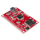
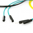
It's now time to hook up your Logomatic to your system of choice for logging. For our example, we will be hooking the Logomatic up to an analog temperature sensor, the TMP36 and some jumper wires. Make sure to solder header pins of your choice to the Logomatic for a secure connection. We will be logging the temperature readings to our microSD card.
Required Materials
To follow along with this example, you will need the following materials. You may not need everything though depending on what you have and your setup. Add it to your cart, read through the guide, and adjust the cart as necessary.


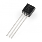
Temperature Sensor - TMP36
SEN-10988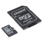
Circuit Diagram
Below is a diagram of connecting an analog temperature sensor to one of the Logomatic's ADC pins.
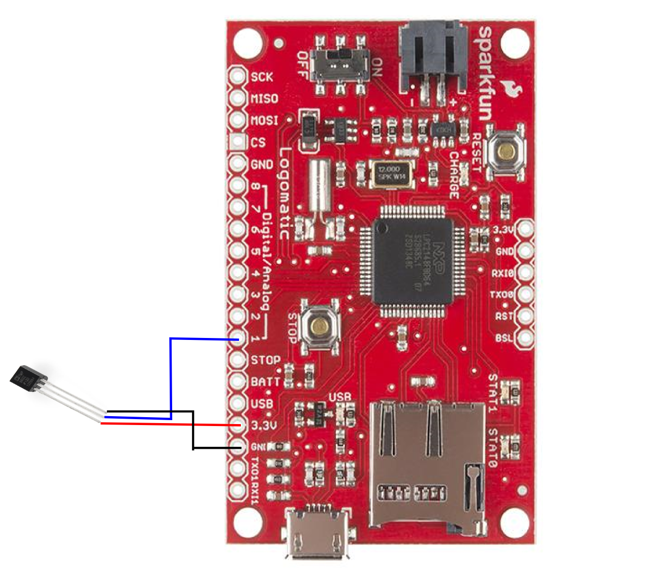
The connections above are as follows:
TMP36 → Logomatic
VCC → 3.3V
Signal → A0
GND → GND
Operation
Now that you know how the Logomatic works and have it connected, it's time to power it up. Set your configuration however you like. In this example, we'll set the configuration file to read temperature on analog pin 1 at a rate of 100Hz and log the raw analog values in ASCII format like so:
MODE = 2
ASCII = Y
Baud = 4
Frequency = 100
Trigger Character = $
Text Frame = 100
AD1.3 = N
AD0.3 = Y
AD0.2 = N
AD0.1 = N
AD1.2 = N
AD0.4 = N
AD1.7 = N
AD1.6 = N
Saftey On = Y
Make sure the microSD card is fully inserted in the microSD slot with a LiPo battery and turn the switch to the ON position to begin logging! The two status LEDs will blink at you rather quickly during the initialization, then the unit will go to work with the settings you chose. The only further indication of operation that you will see is when one of the two data buffers logs to the SD card, STAT0 for buffer # 1 and STAT1 for buffer # 2. These will be very quick "blips" because the LEDs are only on during the write process, between 20-40ms.
When you are done logging, press the STOP button before shutting off the unit to be sure that any unfilled buffers are logged to the SD card and all the interrupts are disabled.
The Logomatic will create up to 256 log files in text format, numbering from LOG0.TXT to LOG255.TXT. The most recent log file will be the one with the highest number.