LogicBlocks & Digital Logic Introduction
 jimblom
What is Digital Logic?
!!!
What is Digital?
Electronic signals can be divided into two categories: analog and digital. Analog signals can take any shape and represent an infinite number of possible values. Digital signals have a very defined, discrete set of possible values -- usually only two.
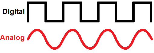
Many electronic systems will use a combination of analog and digital circuits, but at the heart of most computers and other every day electronics are discrete, digital circuits.
What is Digital Logic?
We humans are (mostly) logical beings. When we make decisions and act upon them, logic is working in the background. Logic is the process of evaluating one or more inputs, weighing them against any number of outcomes, and deciding a path to follow. Just like we apply logic to make all of our decisions, computers use digital logic circuits to make theirs. They use a set of standard logic gates to help propogate a decision.
For an in-depth look at digital logic, check out our Digital Logic tutorial!
Where Do We See Digital Logic?
There is logic in all circuits. A connection to a power source is an example of an AND. Only if both power AND ground are connected will the circuit allow electricity to run through it.
Where else? Everywhere! The traffic light in a city uses logic when pedestrians push the walk button. The button starts a process that uses an AND logic gate. If someone pressed the walk button AND there is a red light for traffic where the pedestrian will be walking, the walk signal will activate. If both conditions of this AND statement are not true, the walk signal will never be illuminated.
Inputs and Outputs
A digital logic circuit uses digital inputs to make logical decisions and produce digital outputs. Every logic circuit requires at least one input, before it can produce any kind of output.
Digital logic inputs and outputs are usually binary. In other words they can only be one of two possible values.
There are a number of ways to represent binary values: 1/0 is the least verbose and most common way. However, you may also see them in a boolean representation like TRUE/FALSE or HIGH/LOW. When the values are represented at a hardware level, they might be given actual voltage levels: 0V [Volts] is a 0, while a higher voltage - usually 3V or 5V - is used to represent a 1.
| 1 | 0 |
| HIGH | LOW |
| True | False |
| 5V (Volts) | 0V |
Logic Gates
To make their logical decisions, a computer will use any combination of three fundamental logic functions: AND, OR, and NOT.
- AND -- The AND function produces a TRUE output if and only if all of its inputs are also TRUE.
- OR -- An OR will prove TRUE if any (one or more) of its inputs are also TRUE.
- NOT -- The NOT operator has only one input. The NOT operator negates its input, which means the output will be the opposite of the input.
Each of those functions can be realized using logic gates. Logic gates are what we use to create digital logic circuits. They're the building blocks of computers and other electronics . They take one or more inputs, perform a specific function (AND, OR , NOT, etc.) on them, and then produce an output based on that function.
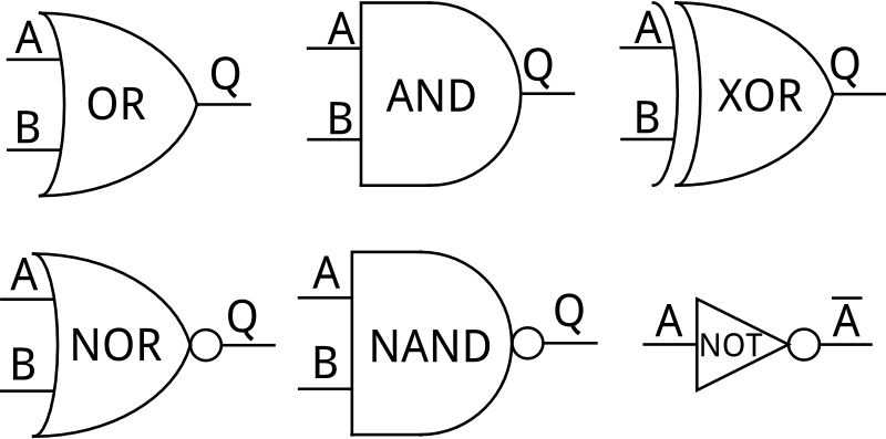
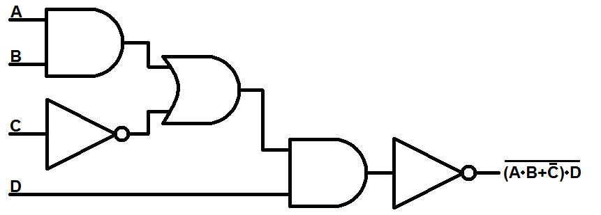
Logic gates all have specific circuit symbols, just like resistors, capacitors, and inductors. And, just like standard electronic component symbols, logic gates can be diagrammed in a schematic by connecting their input and output lines together.
Truth Tables
The 'logic' of a logic gate or function can be represented in a number of ways including truth tables, venn diagrams and boolean algebra. Among those, truth tables are the most common. Truth tables are a complete listing of every possible input combination, and the output they produce.
All inputs are arranged on the left side of the table, while the output is on the right. Every row of the table represents one possible input combination.
| Input A | Input B | Output Y |
|---|---|---|
| 0 | 0 | 0 |
| 0 | 1 | 0 |
| 1 | 0 | 0 |
| 1 | 1 | 1 |
Above is the truth table of an AND gate. An AND gate has two inputs and one output, so the truth table has two columns for input and one column for output. Two input values means there are four possible input combinations: 0/0, 0/1, 1/0, and 1/1. So, the AND gate's truth table will have four rows, one for each combination of inputs. The only case where the output of AND is 1 is when both inputs are also 1.