LogicBlocks & Digital Logic Introduction
The Blocks In-Depth
On this page we'll dig into the gritty details of each component in the LogicBlocks kit. We'll talk about what each block's purpose is, examine their truth tables, and look at what other blocks they can plug into.
Here are some quick-links to the blocks we'll be covering on this page:
- Input LogicBlock
- AND Gate LogicBlock
- OR Gate LogicBlock
- NOT Gate LogicBlock
- Power LogicBlock
- Splitter LogicBlock & Feedback Cable
Input LogicBlock
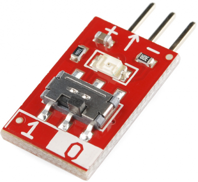
The Input Blocks make the LogicBlocks world go 'round. These small rectangular blocks have one male connector, which plugs into the female input pins of gate blocks, power blocks, and splitters.
Each Input Block has a two-position switch, which you'll use to set the block as either 1 or 0 (TRUE or FALSE, ON or OFF).
A green LED on the Input Block represents the value it outputs. An illuminated LED indicates that the block is set as 1. If the LED is off, the output value is 0.
AND Gate LogicBlock
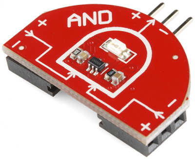
The AND LogicBlock is a two-input, single-output AND gate. The block is in a "D shape", much like the AND gate circuit symbol. The two female input headers are located on either side of the AND Block. The output of the AND Block is located at the middle-top.
You can connect either an Input Block or the output from another Gate Block to these inputs. The male output header can be plugged into either the input of another gate or a Power Block.
Each AND Gate Block has a single blue LED, which represents the output of the gate. If the LED is on, then that means the AND Gate is producing a 1 (TRUE, ON) at the output. If the LED is off, then the AND Gate's output is 0.
AND Truth Table, Circuit Symbol, Boolean Notation
Here's a truth table for the AND Block:
| Input A | Input B | Output |
|---|---|---|
| 0 | 0 | 0 |
| 0 | 1 | 0 |
| 1 | 0 | 0 |
| 1 | 1 | 1 |
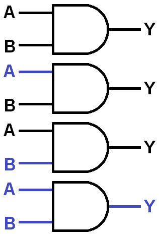
And the circuit symbol for an AND gate, which you'll get very used to seeing:
The boolean equation symbol for AND is the centered dot (·). For example, the gate above could be represented by the equation: A · B = Y.
OR Gate LogicBlock
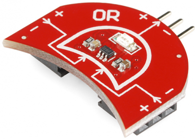
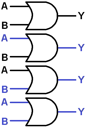
The OR LogicBlock is a two-input, single-output OR gate. The block is shaped like and OR gate circuit symbol -- a convex arc on the output side, and a concave arc on the input side. The two female inputs are located on either side of the OR Block. The output of the OR Block is located at the middle-top of the block.
You can connect either an Input Block or the output from another Gate Block to either of the two inputs. This male output connector can be plugged into either the input of another gate, or a Power Block.
Each OR Gate Block has a single yellow LED, which represents the output of the gate. If the LED is on, that means the OR Gate is producing a 1 (TRUE, ON) at the output. If the LED is off, then the OR Gate's output is 0.
OR Truth Table, Circuit Symbol, Boolean Notation
Here's a truth table for the 2-input/1-output OR gate:
| Input A | Input B | Output |
|---|---|---|
| 0 | 0 | 0 |
| 0 | 1 | 1 |
| 1 | 0 | 1 |
| 1 | 1 | 1 |
And the circuit symbol, shaped much like the block itself:
We can represent digital logic using boolean equations. The boolean equation symbol for OR is the plus sign (+). Here's the boolean equation for the OR circuit above: A + B = Y.
NOT Gate LogicBlock
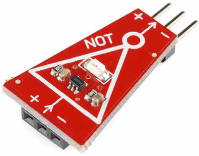
The NOT LogicBlock is a single-input, single-output NOT Gate. The Block comes in a trapezoid shape (it's as close as we could get to the triangle-shaped NOT gate circuit symbol). The female input connector is located on the side with the larger edge. The output of the NOT Block is located on the smaller edge.
You can connect either an Input Block or the output from another Gate Block to this input. This male connector can be plugged into either the input of another gate or a Power Block.
Each NOT Block has a single red LED, which represents the output of the gate. If the LED is on, then that means the NOT Gate is producing a 1 (TRUE, ON) at the output. IF the LED is off, then the NOT gate's output is 0.
NOT Truth Table, Circuit Symbol, Boolean Notation
A NOT gate is often called an inverter because it inverts any signal it receives. A 0 turns into a 1, and a 1 turns into a 0. An inverter's truth table looks something like this:
| Input A | Output |
|---|---|
| 0 | 1 |
| 1 | 0 |
When writing boolean equations, the NOT operation is usually indicated by a bar over any variables it inverts. For example the boolean equation for the circuit above would simply be:  .
.
Power LogicBlock
No electronic circuit can work without some form of power. Enter the Power Block!
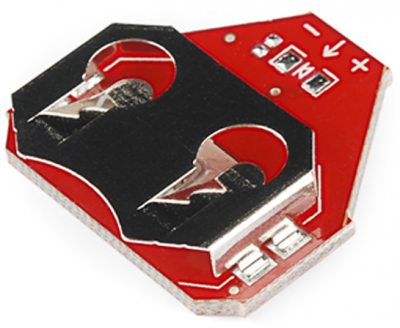
The Power Block runs on a single 20mm coin cell battery, which optimally provides around 3V, and should last for quite a while. The LogicBlocks can work at voltages between 2 and 5V, and they consume very little current.
The Power Block has a single female connector, which should be connected to the output of a Gate Block. Only one Power Block should be connected in any circuit.
The Power Block is the final piece to any LogicBlock circuit. It should be connected to the output of the very last Logic Block gate.
Splitter LogicBlock and Feedback Cable
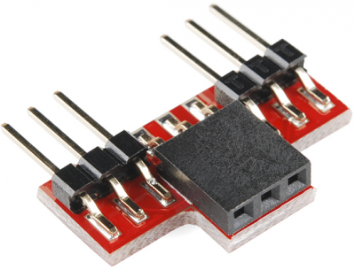
The Splitter Block allows the output of one Block to feed into the inputs of two separate Blocks.
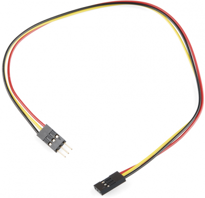
For more advanced circuits you'll want to spread inputs to multiple gates, or add feedback. This is where both the Splitter Block and Feedback Cable come in handy. Often the Feedback Cable will be connected to one of the two Splitter Block outputs.
The Feedback Cable is made of three separate wires -- colored red, yellow, and black. Red should always be connected to the + pin, black to the − pin, yellow will pass the signal through.
